How to Build the PinSim Virtual Reality Pinball Machine
Jeremy Williams' build guide for his PinSim VR pinball cabinet!
The PinSim cabinet is essentially the first eight inches of a real pinball table. I designed it to play VR pinball games, but it works just as well as an interface for traditional flat screen pinball games. The following instructions will help you make one of your own. I’ll cover the most basic build first and then look at a few optional upgrades.
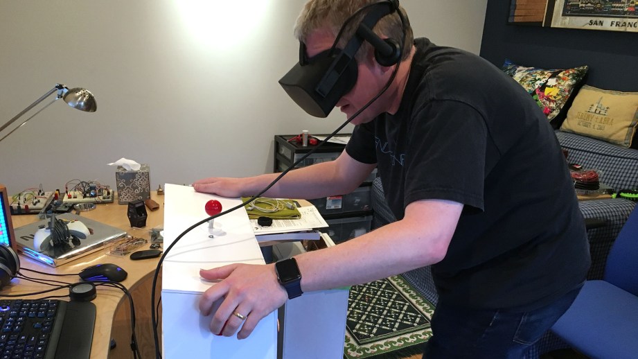
The electronics are based on Teensy LC and employ the incredible MSF-XINPUT library by Zachery Littell. This new library fools the computer into thinking the Teensy LC is an Xbox 360 gamepad, thus minimizing latency and maximizing compatibility. It even supports force feedback rumble! Zack spent time improving his library to assist with this project, so major thanks to him.
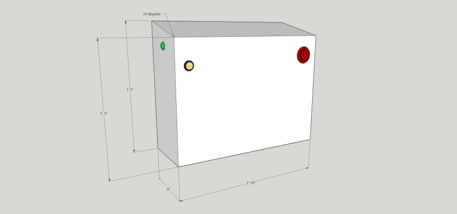
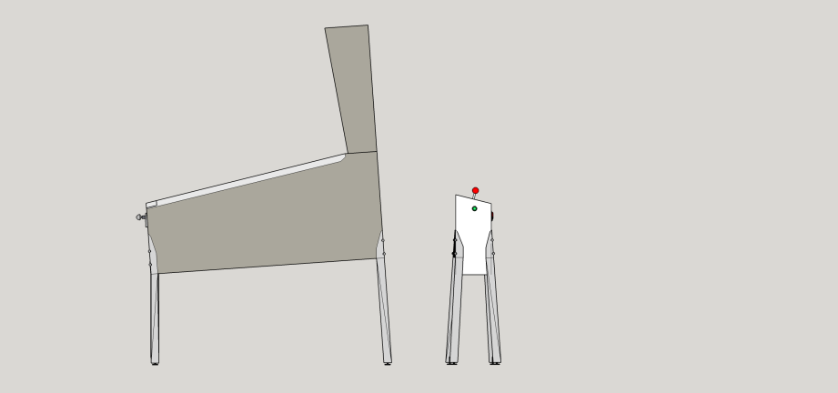
There are many possibilities for cabinet material. My original cabinet was cut from foam core but wood will provide a more lasting frame. Just make sure to consider the material thickness before cutting the sides of the cabinet. The graphics below illustrate the exterior dimensions and hole placements, but the diameter of the drill holes will depend on the buttons you choose to use.
Let’s start with the parts you’ll need.
Parts
- Teensy LC w/Pins
- PinSim PCB
- Basic Stranded Wire
- (2) 30mm Arcade Buttons for flippers
- Small Arcade Joystick
- Full Sized Breadboard
- ADXL345 – Triple-Axis Accelerometer
- Start Button
- Launch Ball Button
- (4) Pinball Legs
- (8) Leg Bolts
- (4) Leg Brackets
- (4) Leg Levelers
- (4) Cabinet Leg Protectors (optional)
Parts Notes
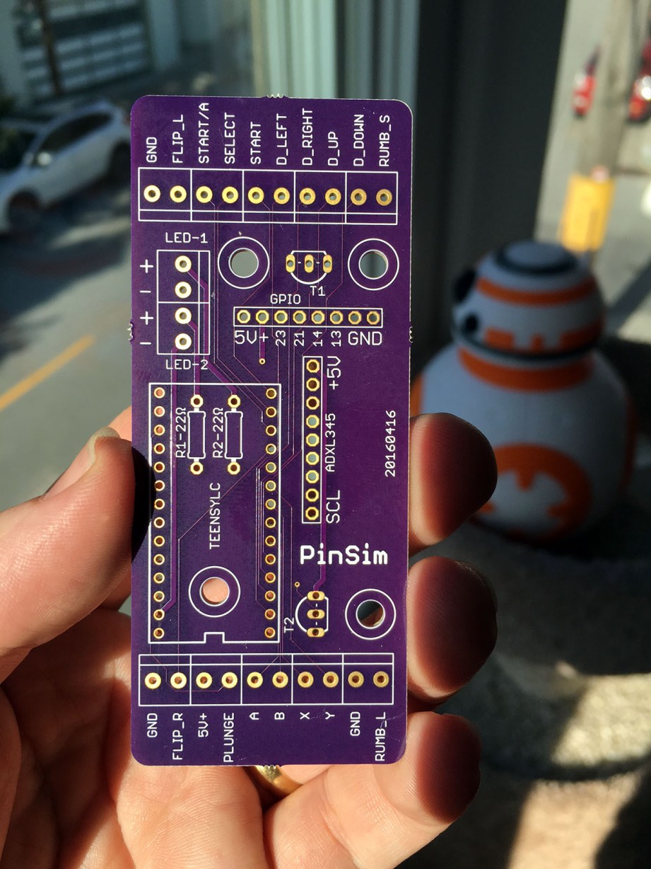
PCB: You can use a Large Breadboard but I strongly recommend picking up the PCB I designed from OSH Park to simplify the wiring. They come in sets of three, so you can share a set with friends or just keep the spares.
Teensy LC: While Teensy LC is pin-compatible with the more expensive Teensy 3.2, I recommend using Teensy LC due to the support for 20mA current on a few pins that I use for lighting optional LEDs. You can buy a pre-flashed Teensy LC from me at the link above.
Joystick: This is used to conveniently navigate game menus, but you could use a gamepad instead. If you do include a joystick, just mount it according to its mounting plate wherever you think it fits best.
Accelerometer: The accelerometer is used to simulate nudging the table. Make sure to mount the PCB in the precise orientation and position indicated below for the most accurate readings.
Cabinet Build Instructions
Cut your cabinet sides based on the dimensions below and drill holes for your buttons, joystick, and legs, centering where indicated. The holes for the leg bolts can be a little tricky, especially with wood, because they enter at the corners at 45 degree angles. I recommend drilling these from the inside out.
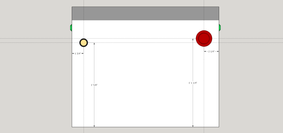
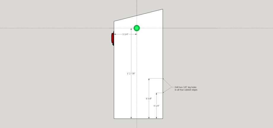
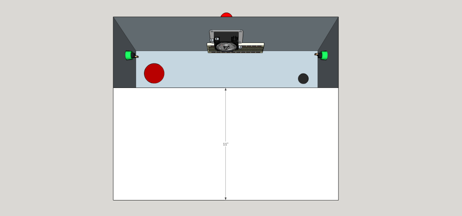
Wiring Up the Controls
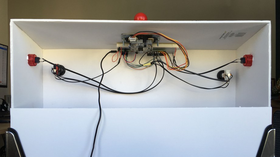
Mount the PCB/Breadboard on the underside of the top panel so that the accelerometer is horizontally center and the text “ADXL 345 Digital Accelerometer” is facing the player. This probably means that the PinSim PCB is mounted between the joystick and the front edge of the cabinet like in the photo below.

Wire everything up according to this image if you’re using a breadboard or just use the labeled terminals if you’re using my PCB. Note that all components can share a common ground wire. The joystick pinout can be found here.
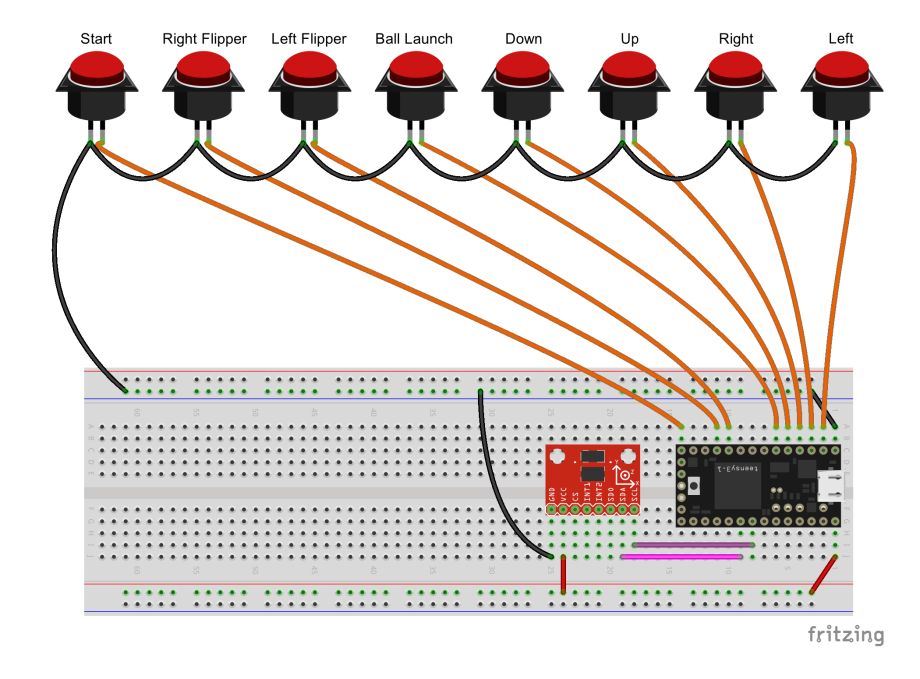
IMPORTANT: If you’re not installing a plunger, connect the “PLUNGE” terminal on the PCB (Teensy pin 15) to GND. This will disable the plunger. Failing to do so will leave the pin “floating,” causing the virtual analog stick to move unintentionally.
If you didn’t buy a Teensy LC from me, which comes with firmware already installed, download the compiled firmware and flash your board using the Teensyloader application. You’re welcome to compile the firmware yourself but the XInput library does require some Teensyduino files to be overwritten. You can find instructions on GitHub.
You’re done! Plug in the Teensy LC using a USB micro cable and it will power up. You can test the PinSim by launching the Windows USB Game Controllers app from the Control Panel.
PinSim Upgrades
LED Light
Let’s put the light inside the Start button on the front of the cabinet to use. If you connect it to the LED-1 terminal on my PCB (or pin 16 on a Teensy LC), it will blink when powered up. It actually flashes between 1-4 times, mirroring the 4 LEDs around the Xbox logo on a real gamepad. This is a useful indicator since game software often requires controller #1.
Replace the 555 light bulb inside the Start button with a white LED and wire it up (just make sure to run it through a 22 Ohm resistor like it does on my PCB). If you have a 3D printer, you can print my 555 bulb holder.
You can do the same for the bulb inside the Launch Ball button and connect that to LED-2. It will remain steady on.
Rumble Feedback
You want force feedback, right? You’ll need to buy some spare Xbox rumble motors from eBay but they usually run less than $10/pair shipped. If you have a 3D printer, you can also print a couple of my handy mounts.
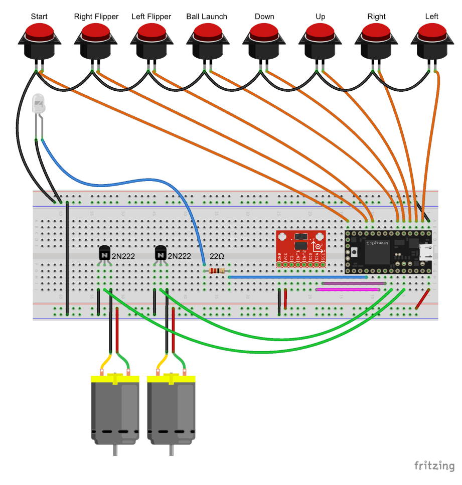
Wiring the previous two upgrades is pretty straight forwarding using my PinSim PCB, but here is the breadboard wiring if you need it.
Arcade Buttons
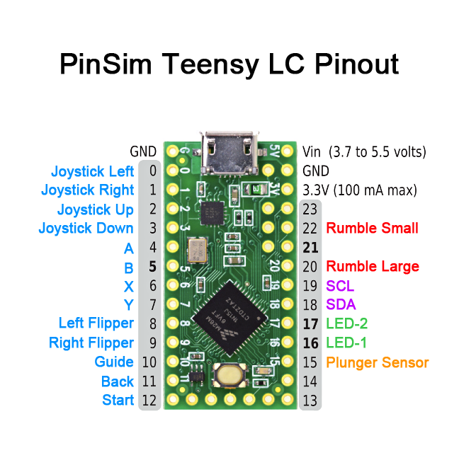
You don’t have to stop at flippers. Especially if you have the joystick installed, why not add more buttons and use PinSim as a potential upright arcade controller too? Just drill more holes beside the joystick and connect them to the labeled terminals on the PinSim PCB. For the breadboard crowd, the Teensy LC pinout is as follows.
Plunger
What about a real pinball shooter? I have to warn you, this is a lot of extra work for minimal payoff. The plunge is important for hitting skill shots, but not much else. That said, it does complete the look of the cabinet and you need a plunger for certain Pinball Arcade tables (flat screen, not VR… yet!). For simplicity I’m going to assume you have access to a 3D printer for mounting the sensor hardware.
Here are the additional parts required:
- Shooter assembly
- Shooter mounting plate
- (3) 10-32 X 5/8″ Machine Screws
- Brown (low tension) shooter spring
- Sharp GP2Y0A51SK0F Analog Distance Sensor 2-15cm
- 3-Pin Female JST ZH-Style Cable
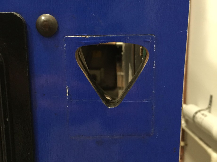
The cabinet hole for a plunger is huge and triangular shaped. And while we can place the plunger at the proper height, we need to fudge authenticity a little and move it an inch to the left in order to leave room for our digital sensor gear later on. Use the following pictures to cut your cabinet hole.

Fire up your 3D printer and print the mount for the distance holder.
Then print the plunger disc that attaches to the shooter rod and reflects the IR signal back to the sensor. Just remove the rubber tip from the plunger, slide on the disc, and replace the rubber tip.
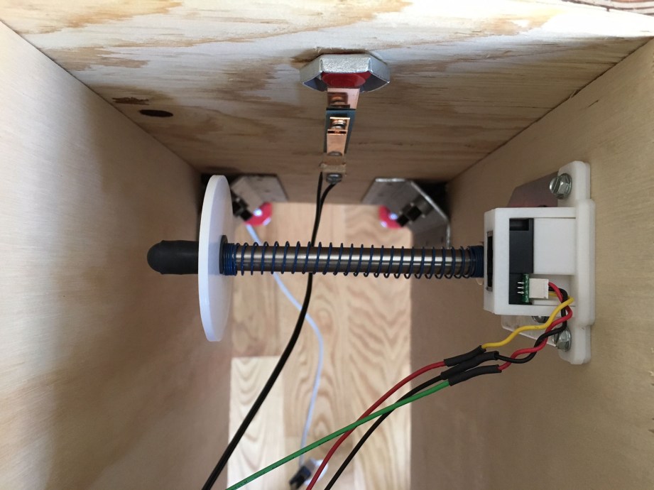
Connect the JST cable to the sensor jack and assemble the mount. Attach the assembled sensor just above the plunger with the wires facing up. The thin, angled plastic mount component should go between the mount and the cabinet, tilting the sensor slightly downward so it points toward the plastic disc. Finally, connect the wires as follows:
- Black to Ground
- Red to 5 Volt terminal on PinSim PCB
- White to Plunge terminal on PinSim PCB

Finally you need to configure the plunger. With the Teensy LC USB cable unplugged, hold down the Start button (Teensy Pin 12) and plug in the USB cable. After a moment the LED-1 should flash rapidly. Slowly pull the plunger all the way out and then slowly allow it to retract all the way back in. The LED should flash rapidly again, and then blink normally. You can repeat this process as necessary, but the settings are permanently stored between power cycles.
While you’re at it, you’ll probably want to re-wire the cabinet Start button to the “A” button and add a second cabinet button to act as the 360 Start button. And as long as you’re adding a plunger, I’m going to assume you’re deep enough into this that you understand why.
See? I told you it was a lot of extra work! If you’re up to the challenge, it’s definitely gratifying.
I just completed assembling my second PinSim, thanks to the great help of my friend and carpenter Christopher Mann. It includes all of the above upgrades plus real flipper buttons and leaf switches (if you do this, make sure to sand down the tungsten contacts). Next up, tidying the cabling and a third cabinet with more precise measurements and a nice exterior finish. Fun!

All photos and images by Jeremy Williams
58 thoughts on “How to Build the PinSim Virtual Reality Pinball Machine”
Leave a Reply
One Day Builds
Adam Savage’s One Day Builds: Life-Size Velocirapt…
Adam embarks on one of his most ambitious builds yet: fulfil…

Show And Tell
Adam Savage’s King George Costume!
Adam recently completed a build of the royal St. Edwards cro…
All Eyes On Perserverance – This is Only a Test 58…
We get excited for the Perserverance rover Mars landing happening later today in this week's episode. Jeremy finally watches In and Of Itself, we get hyped for The Last of Us casting, and try to deciper the new Chevy Bolt announcements. Plus, Kishore gets a Pelaton and we wrack our brains around reverse engineering the source code to GTA …
Making
Adam Savage in Real Time: God of War Leviathan Axe…
Viewers often ask to see Adam working in real-time, so this …

One Day Builds
Mandalorian Blaster Prop Replica Kit Assembly!
Adam and Norm assemble a beautifully machined replica prop k…
House of MCU – This is Only a Test 586 – 2/11/21
The gang gets together to recap their favorite bits from this past weekend's Superb Owl, including the new camera tech used for the broadcast and the best chicken wing recipes. Kishore shares tips for streamlining your streaming services, and Will guests this week to dive into the mind-bending implications of the latest WandaVision episod…

One Day Builds
Adam Savage’s One Day Builds: Royal Crown of Engla…
One of the ways Adam has been getting through lockdown has b…

Making
Adam Savage Tests the AIR Active Filtration Helmet…
Adam unboxes and performs a quick test of this novel new hel…
Making
Weta Workshop’s 3D-Printed Giant Eyeballs!
When Adam visited Weta Workshop early last year, he stopped …
One Day Builds
Adam Savage’s One Day Builds: Wire Storage Solutio…
Adam tackles a shop shelf build that he's been putting off f…












If/when some pinball hits the Vive, I might have to make this thing! So awesome. Great job.
Thanks for sharing. I wonder what the response would be from CAX crowd.
Great work Jeremy!
The last time I played any pinball game on a computer was Pinball Illusions on a A500. Maybe it’s time to revisit the genre when I get my rift and build this if I get hooked. But maybe a more compact model that I can clamp on to my desk
I’ve thought about that but I’m not about to bring my Rift down there for 100 people to stretch out and sweat on.
Yeah! I had a friend in college with an Amiga and when I first saw Pinball Illusions I was amazed by the graphics and music. I was all over that series when it finally came to PC.
Look so cool, such a great idea and Job on it Jeremy.
It’s definitely a tempting build to try. As someone who recently got into pinball (played it when I was real young, but in the arcades pinball=instant quarter drain, vs other games that I could get longer plays on), but will likely never spend too much time on physical machines (no space/money for collecting, no good locations near by to play) “digital” pinball is it. Add in VR and it seems like the best compromise you can make.
I’ll probably hold out until there is support from more software. I’d love to play the classic tables, but it seems like “realistic physics” that match how the game plays in the real world is still something that is not guaranteed in most pinball software. I thought I was “good” at pinball after playing The Pinball Arcade a bunch, until I stepped in front of an actual machine and quickly learned how wrong I was. After that I’d very much like the idea of a digital/VR pinball experience that can help translate into skills/experience on the real tables.
Welp… this is too awesome. I’m all in. I’ve ordered everything on the list, including the plunger hardware and distance sensor. I’m going to CNC the cabinet panels and give it some nice trim. Will post pics when it’s done… eventually. Sometime next decade, likely.
If anyone’s curious about the cost of making one of these (like my wife), the total for all of the hardware listed here came to $308.18 USD, assuming I didn’t miss anything. And, as an added bonus at no additional cost, the numerous purchases in rapid succession generated not one, but TWO fraud alerts on two of my credit cards. Apparently pinball equipment isn’t a common purchase for me. 🙂
By the way, that total is including shipping (via the cheapest shipping options), and I have Amazon Prime for free shipping on the stuff from Amazon.
I can’t wait to build this thing. I’ve been playing Pinball FX2 on the Oculus Rift with the Xbone controller, and I can’t put it down. It’s one of the best games on the Rift right now. Thanks, Jeremy, for sharing this project!
This is awesome I think this setup could be used with other switches to emulate other environments in vr. Or dedicated buttons for computer programs and games
Which flipper buttons do you use for the Leaf switch build? Is there a particular model of the Leaf switches to use?
Here you go…
Flipper buttons: http://www.pinballlife.com/index.php?p=product&id=1692
Leaf Switches: http://www.pinballlife.com/index.php?p=product&id=597
so I made one of my own. I flashed the teensy and it comes up on Windows 7 as an unspecified USB device. Is there a particular game controller driver I should use? I found the x360ce.com site.
Ok I got it to work. My problem was I ordered a Teensy 3.2 from OSH park when I ordered the PinSim PCB. So make sure you get a Teensy LC. This is my first teensy project and I am not as familiar with the product line as I am with arduinos and raspberry pis. I tried to re-compile the source for the Teensy 3.2 but got a compile error. I decided to buy another processor instead of debugging the code. I will do some more testing and hopefully I will be playing VR pinball very soon!!!
Ive purchased and assembled everything, but the PC doesn’t recognize the teensy+pcb is plugged in. I purchase the teensy from you so I have not messed with any firmware and such. Im using a new install of windows 10 on a skull canyon NUC. Ive tried just the teensy without the pub and controls too (I bought 2 of them) with the same result. Any suggestions? Thank you!
I determined that my issue mentioned above was caused by the two usb cables I tried. Things work fine using a PS4 controller charging cable.
Hoping someone can help. I built the cabinet, wired everything up, and flashed the TeensyLC. The cabinet is now being recognized as a 360 controller (yay!), but none of the buttons / joystick work. This is my first time doing any of this so I may be missing something obvious. Do I need to download those those libraries listed in the ReadMe?
I got it working. Turns out the accelerometer configuration is slightly different than fritzing diagram. Gnd and 3V3 are reversed and there is one additional pin that is not shown as well. 🙂
Hey guys, I got everything working and it’s awesome but I seem to have a strange issue. The accelerometer seems to work once and then shut off. Does anyone have any idea why this might be?
I would die to be able to buy one of these. Looking at the instructions, just not something I am going to be able to do on my own,
Hey Jeremy, a few quick questions. I’ve built my box, but I’m unclear on a few things regarding the electronics.
1) Is it possible to use more than 4 arcade buttons using your PCB? If not, what modifications would need to be made when using a breadboard to hook up additional buttons? I know that the XInput API should support some additional buttons if you get “creative” with your mappings. I see that you have 6 buttons on your controller (plus a start and back?), but 2 of them aren’t fully wired in. Was that a shortcoming of the PCB, or just that you didn’t bother?
2) It looks like some things need to be soldered to your PCB and/or the Breadboard. Specifically the Accelerometer, the transistors, and the resistors. Is that correct, or can I leave my soldering iron unplugged.
3) I found out that I need to order PAL Nuts to mount the pinball flipper buttons, but I don’t know what kind of screws I need to mount the leaf switches. Any suggestions?
4) Finally, I’ve bought a plunger and the machine screws you mentioned, but the 3 mounting holes on the shooter assembly (http://www.pinballlife.com/index.php?p=product&id=527) don’t appear to be threaded at all. Is that standard? Do the screws just bite into the assembly’s metal when you screw them in, or do I have a defective piece?
Thanks for all the help.
Looks like the Vive is getting Pinball FX2 on the 29th, ordering my parts today!
What gauge of wire are you using?
I have tried to get this working properly. Some of the buttons work in FX2 Piball but not all.
Anyone want to built me one of these and I will pay them?
I have the same question about using more than 4 buttons, and also noticed that 2 of the 6 buttons in the picture are not wired in >.> Were you able to get 6 buttons working? I’d be super interested in hearing your solution if so 😀
This is such a great project, thanks for sharing your design!
So there are a couple of things you’ll need to do in order to get more than 4 arcade buttons functioning. If you look at the PCB note that there are 4 pins labeled “13, 14, 21, 23” in the GPIO section. Check out the Teensy pinsim firmware source code and you’ll see that 13 and 14 are your analog stick press buttons, and 21 and 23 are your analog triggers. You’ll want to wire 2 of your arcade buttons into 13 and 14. Those will then register as R3 and L3 (or however you’re used to mapping those in game). 21 and 23 are analog signals, and so not especially useful for digital on/off buttons. They may work, but I haven’t tried it and aren’t the route I took.
That gets you up to 6 “playable” buttons, plus 2 trigger buttons, Start, Select, and Guide. But what if you want a full fighting stick? Then you need 8 “playable” buttons. The XInput API doesn’t support that. So you need a work around. That’s when I realized that what you really want isn’t a pinball and arcade controller. You want a pinball or arcade controller. By wiring 2 of your arcade buttons in parallel with your flipper buttons you can have either one of them register as right and left triggers. Since you literally can’t use the controller as both a pinball and arcade stick at the same time (unless you have 4 arms) then there’s no problem with multiple buttons doing the same thing.
Fair warning, I’m only 90% done. I haven’t wired in the last 2 (13, 14) buttons or my plunger yet, so this is all untested(hah). But theoretically it should work. The more interesting part will be wiring up all of the other lights. I’ve not started looking into how to link multiple LEDs together (each of my arcade buttons has one), much less control the multicolored LED joystick I went with. It might turn out that the breadboard would have been a better decision, but it’s possible that the Teensy won’t support that anyways.
Good luck with the build!
This is super helpful info, thank you! I was starting to go down similar lines of thinking regarding wiring two buttons to the same input, but wasn’t too sure about how that would work. I’m patiently waiting while my components are delivered, but hope to start working on the electronics soon. I feel a lot better about making the six button fighting stick portion of the build work now after reading your break down though. Thanks again!
Finally finished mine! Everything is working well, including the 6-button configuration. I took your suggestion and wired them in parallel, thanks again.
@jungletech Wow, looks fantastic! How’d you get the graphic on there?
I’m getting ready to put mine together tomorrow, just noticed that the circuit board calls for two resistors underneath the Teensy, do I just solder them flush and then keep the Teensy raised up above them? Or do I want to solder them so that they’re on the reverse side of the board?
Can’t seem to edit my last post, I now realize that the small stand-offs on the Teensy will allow room for the resistors to go underneath. Printing off the parts for the LEDs/rumble motors, looking forward to the build tomorrow!
Wow so much awesomeness in here! Sorry I haven’t been monitoring this thread. Please feel free to nudge me on Twitter () if I can be of help. Glad to see most people are finding solutions to their problems.
Great project, Jeremy. Question: Where are you pulling the 5V source from? A wall wart?
Sorry if I missed something in the instructions.
Sorry for the late reply. The Teensy gets connected via USB and behaves like an Xbox controller. It gets all its power over that line.
Hello everyone, first I want to thank JEREMY WILLIAMS for this great idea and share this work. I have a situation that I would like to discuss if it has happened to them and if there is any way to fix it !. I have everything ready and working. My PINSIM has a plunger and Windows recognizes it as Y, but the game of Zen Pinball does not. I have dealt with the xbox mapping and without, everything works except the plunger in the game.
Here is the PINSIM that I made:
Has anyone else noticed (Jeremy?) that the screw terminals in the parts list DO NOT fit on the PCB from the parts list? They are slightly too wide, so in order to solder them to the board, they must be put tilted (one pi tilted up)… they end up looking like crooked teeth once soldered in.
Also, it’s not explicitly stated in the instructions what the 1×14 Female Headers are for, and I found out the hard way that they are intended to raise the Teensy LC up above the screw terminals;.. if you solder the Teensy LC directly to the board, its USB port will be blocked by the 5V and Plunge terminals… use the female headers to raise the TLC up above the screw terminals.
Finally got mine built…where do the 2 buttons left of the joy stick go? I have left as “back” and right one as “guide”. In the controller emulator the “guide” button does not show up as anything. Also I used the 5V for the plunger to power backlit buttons…do these need 22 ohm resistors like the start and launch buttons?
Thanks for any help here.
J
This project is fantastic, thank you Jeremy! I dont have much space in my flat so I decided to build a tabletop version. It doesnt look exciting, but works perfectly. Maybe I am going to put some printed foil on it one day. The gap to real machines is really small now in my opinion. I love the rumble and the nudge on Pinball FX2 VR. Also got Zaccaria Pinball but had no luck on activating rumble and nudge there. I tried a lot of tutorials but had no luck yet. Any suggestions here, has anyone able to get rumble and nudge running on Zaccaria? Or is it just not possible? I’d get in touch with the designers then. Thanks for you help guys.
Hello I am new to Arduino I would like to know if your system can be put in Bluetooth
Anybody has tested it with HTC Vive?. Thanks a lot.
I do not have 2 3d printer where can I get the mount and disk for Sharp It sensor use on the plunger.
Can you have the plunger and the launch ball working at the same time? Some games require auto launcher and some have the plunger.
This is a superb project !
Jeremy.. posting this level of detail after putting in all the legwork is
amazing. You ROCK!
I’ve been ordering parts and building the cabinet.
Today I put the electronics together on my newly arrived PinSim PCB
fired it up… Xbox 360 controller recognised.. but no buttons worked
Hmmmmm… triple checked everything… then started reading the other posts
here in a bit more detail.
Having read through them someone else has had this problem. My accelerometer
has a different pin out to the one in the build photos. Ground is reversed with
3v3 and also only has 8 pins not the 9 shown in the original post.
I’ve been unable to get the 8 pin version to work despite changing the pin
out with some spaghetti wiring.
So I re-flashed the teensy with no accelerometer… and bingo… all
working.
I’ve just ordered the 9 pin board as shown in the build pictures. So… just
be aware… it doesn’t work with the 8 pin ADXL345 accelerometer.
Very very cool !
Mini update.
I wired it up yesterday (still havent got the pulnger sensor mount sorted out so that’s waiting… as are the rumble motors.
First crack at it I had all manner of ghosting. Buttons activating other buttons Accelerometer sporadically shutting down joystick taking control of whatever it fancied.
So I took all the very thin wire I was using off in cae it was iterferanace across my spaghettie and re-did it with standard 13 amp mains flex. Only just fits in the screw down terminals on the PCB.
Same problem. seemd to be mostly concentrated between the joystick and the xbox start button… anyway.. long stiory short I took the PCB out of the cabinet again to make certain i hadnt cross soldered an of the terminals. (I hadnt… but I hadnt really cleaned up the flux from teh back of the board either.)
Never had an issue with flux carrying a current before, but after cleaning up everything is working perfectly.
So once again I learn the old lesson of being tidy. Which I have already forgotten again. Happy days !
OK…
all set up and running but the constantly binking LED 1 is making the plunger activate with each blink.
I think the esasist way forwrad is to either to disable that led after initail boot up.
I can see that there are ways to do that in the code but have no idea how !
Anyone able to assist?
Amazing project.
I’ve just built that one, but I don’t know what’s the purpose of Start/A pin.
Checking it out under “game controllers” (Windows 10 settings) it does not show any button pressed.
Can anybody clearify this?
Looks cool, how did you do the graphics on the cabinet?
This is my pinsim. I am incredibly proud of it. The mirror ball you see is the joytick. I did not want to mess with the plexiglass and rails. I did not want anything intruding on the top. I also modified the pinsim software to press the X button when you press start + launch ball and also press B when you press left flipper and joystick up. Had an incredible time building this. The theme took a while to come up with but I am VERY happy with it.
That Pinsim looks great.
Did you guys already recognize that there is new stuff for us.
Visual Pinball is now available in VR (early stage)
https://www.reddit.com/r/oculus/comments/atvkgz/visual_pinball_vr_pinsim/
How hard would it be to tie this in with a Raspberry Pi also inside the cabinet for arcade emulation?
Then just use HDMI from Pi to plug into a TV/monitor.
I’m guessing something like this would work where you just plug the USB output of the teensie to the USB input of the Pi?
https://github.com/RetroPie/RetroPie-Setup/wiki/Xbox-360-Controller
I am having problems with the rumbles. Whwn you say “Hold left flipper on boot to perform a rumble test” what is the meaning? What is the meaning of “on boot” here?
Thanks a lot.
Unfortunately the link for the buttons is now broken. Are these the “sprung” or “unsprung” buttons?
Thank you.
The link to “30mm Arcade Buttons for flippers” works for me. They have springs.
This was exactly what I needed for my project. I wanted a digital
pinball machine, but didn’t want to use up floorspace, so I made a pinball “frame”
instead. I reduced the width of the controller a couple inches and packed everything
into the minimum vertical space I could get away with. (I had to make
compromises like mounting the plunger sideways). The controller sits on a shelf
that is attached firmly to a custom frame that can be mounted on the wall. The
frame includes a monitor, a mini-pc (mounted behind the shelf), and even has a
tiny shelf below the controller to hold a small wireless keyboard. Since the
controller is independent, It can be removed and attached to another computer
as a tabletop controller.
I built a Pinsim controller. However, the usb would randomly disconnect and lose power. I think I finally found the cause after a lot of effort and expense, I disconnected the rumble motors and no drop outs! Now I want to add 2 more motors and power them thru an auxiliary circuit.
Finally finished my Mid-century inspired Pinsim! Took me a ridiculous amount of time and money, but it’s so worth it.
I used a spare Ultimarc I-PAC 2 interface and the Freescale KL25Z controller for nudging and added two brass hooks to store my Oculus Touch controllers during gameplay.
It does in fact work with the 8 pin accelerometer. just make sure you are powering it on your breadboard from the 3.3v power source and not the 5 as in the diagram posted here. That got mine working right away. The 8 pin can’t handle the higher power unlike the 9pin version.
Just bought my PCB board. I’ll order the rest when it comes in. Has anyone made a how to video yet?
Hi just thought I’d share my fix for the rumble motors causing the teensy to hang. This is caused by back emf or noise from the motor brushes feeding back to the controller. Here’s a good article on it: http://www.learningaboutelectronics.com/Articles/Vibration-motor-circuit.php
Do you mind if I quote a few of your articles as long as I provide credit and sources back to your blog? My blog is in the exact same area of interest as yours and my users would certainly benefit from some of the information you provide here. Please let me know if this ok with you. Cheers!
@August 10, 2020 re: rumble motors + 1N4001 diodes & 0.1µF ceramic capacitors:
IT WORKS!! Rumbling my butt off now with no more USB disconnects. Love love love it. THANK YOU!!