


The Volpin Project, Part 4: Taking Shapes
We've got our blueprints, references, and a pretty good idea of how to block out some shapes. Its finally time to glue together some foam, plastic and wood and start making a sci-fi glowing needle space gun.
All right! We’ve got our blueprints, references, and a pretty good idea of how to block out some shapes. Its finally time to glue together some foam, plastic and wood and start making a sci-fi glowing needle space gun.
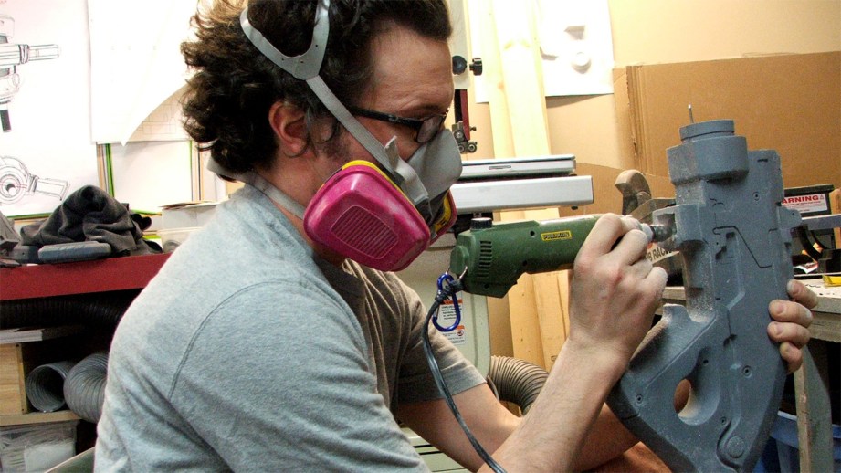
Here’s a standard warning that, while most of us have read it a million times, bears repeating: Whenever you’re working with anything that releases gas, dust, shavings, splinters or particles, wear a respirator! Goggles wouldn’t hurt either if it looks like your material will be shooting particles out violently. I have a dust collector in my shop that’s hooked up to all the tools that spit fine material mist everywhere to help with keeping this crap out of the air. Wear safety equipment like this with everything. Cardboard is technically “non toxic” but you don’t still don’t want to be breathing cardboard dust!
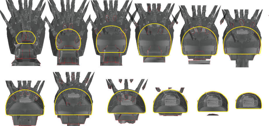
While messing around in Photoshop, I discovered a pretty neat feature in the 3D palette. I have no doubt that people skilled with 3D programs have known about this for ages, but it was a pretty big “aha!” moment for me. In the “3D Scene” menu, you can choose to cross section your model, and even highlight where the cross intersects the part. Words aren’t my forte, so I put together a little animated gif of what this means exactly:

For creating the rear casing, I saved a series of images of the sliced rear section of the gun with the intersecting plane highlighted in red. These were then transferred to Illustrator, and traced into vector format. Since the gun is a series of flat polygons, a little interpretation of the outlines was necessary in order to get a proper curve.
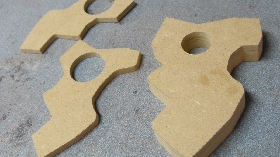
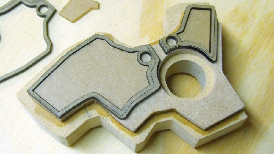
These patterns were transferred onto some ¼” MDF with my laser cutter. Technically you could cut these out completely on a laser, but MDF is a pretty nasty material to go burning holes into, so I decided to just make the patterns here and cut them by hand later on with my scrollsaw.
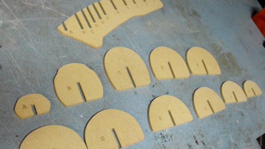
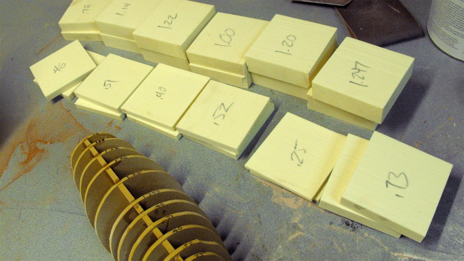
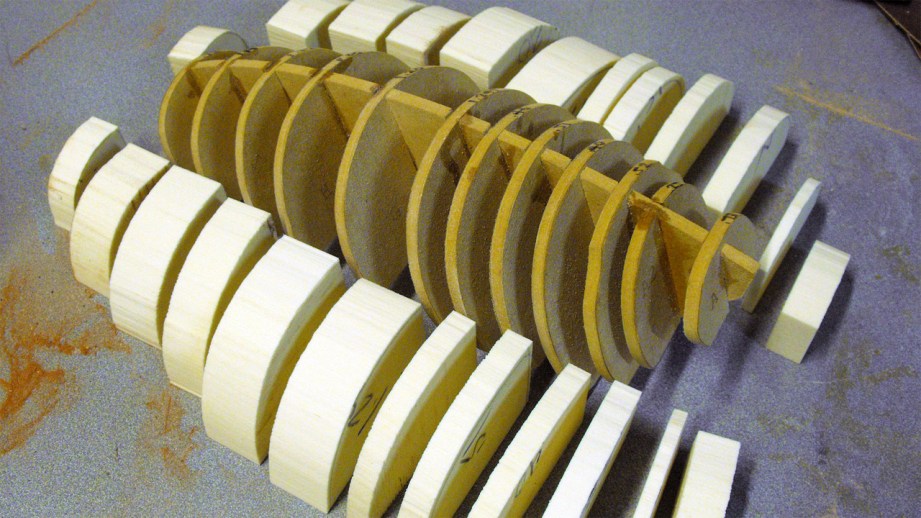
Finished cut pieces. Also convenient if you’re planning on making a model ship, apparently. I discovered there were a few jumps in the shapes from one step to another, so I cut out a few more inserts to make the curve transition smoother.
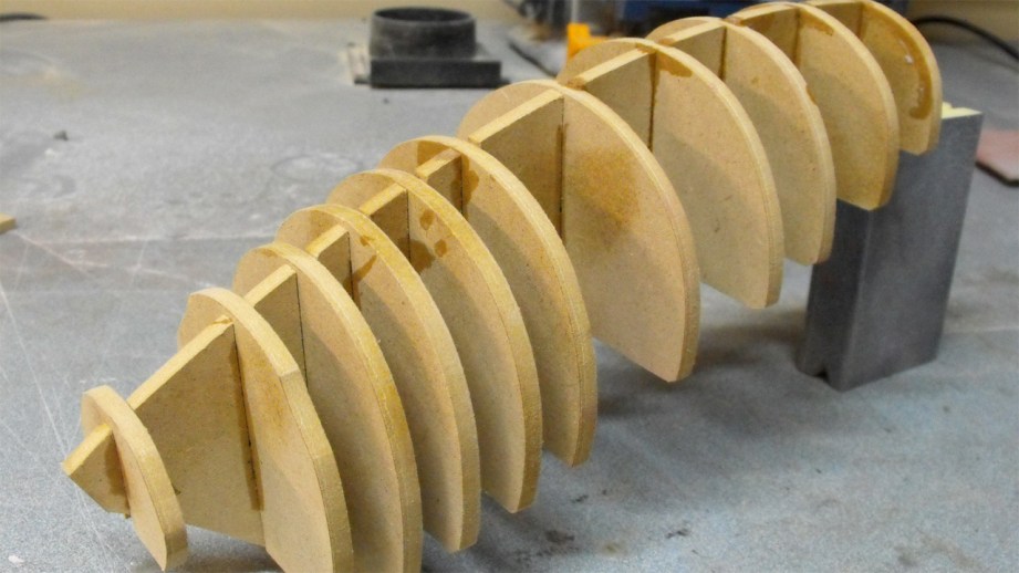
The spaces between were filled in with 5lb urethane tooling foam. Since the gaps were variable in width, I had to spend some time slicing different thicknesses of foam to make sure there were as few gaps as possible. Grab a sharpe and label everything – don’t be sqeamish about making notes directly on the piece you’re cutting or sculpting either. A notebook can be misplaced or the correct page forgotten, but if you write “don’t cut this side, idiot” onto your prop, it tends to keep mistakes from happening.
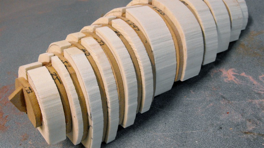
All the sliced sections rough cut and superglued into place. I like to use the really thick “gap filling” cyanoacrylate here, since it will fill the spaces between the foam and the wood well and won’t run down the side of the piece – inevitably gluing your hand to the prop when it does – when you spread it onto the foam.
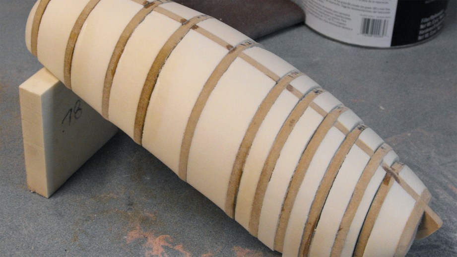
These blanks were then shaped with some 50-grit sandpaper. Very rough stuff, kind of like sanding with a roofing shingle. A while back my dad stumbled onto some overstock sanding belts at a tool thrift store here in Atlanta, and bought me about 30 belts in 50, 80 and 120 grit. I don’t have a 24″ belt sander, but cutting these belts into squares makes for perfect sanding blocks for rough shaping like this. Sanding belts have a thick fabric-like backing and are generally meant to have a longer lifespan than regular sandpaper. While this isn’t really an option for everyone, it has become my preferred method for doing initial rough passes like this.
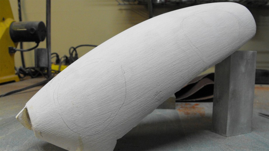
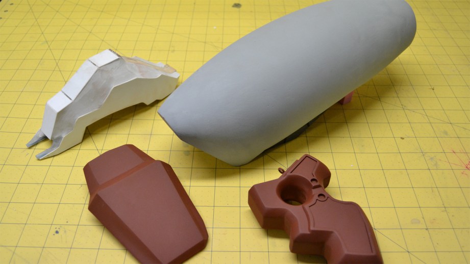
This little foam and wood blimp was then skinned with several passes of bondo to even out the shape. If you’re using urethane foam like I am, you can just slap the polyester filler ont here no problem. If you’re using the pink-or-blue extruded polystyrene foam (insulation foam from Home Depot or LOWES) then you’ll need to seal it first with something like acrylic paint to keep the polyester filler from dissolving the foam underneath.
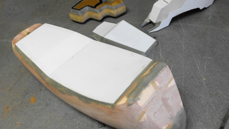
The flat areas on the bottom are a little easier to accomplish. Going back to the blueprints and taking measurements of the lower dimension of the top casing gave me the shapes that were trimmed out of styrene sheet. If you wanted to you could try to sand some bondo into a flat plane to fill in this area, but no sense in making more work when a shortcut will do. The beveled edge sides were also added at this point with some apoxie sculpt.
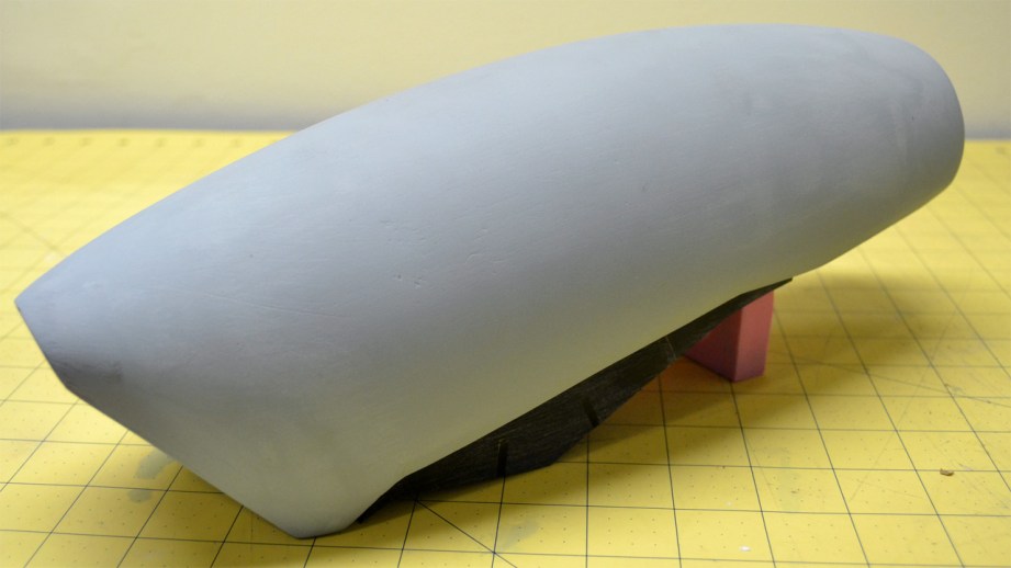
A whole bunch of sanding later and the base form is finished. From here I can start carving panel lines and indentations into the surface for the hexagonal needle chambers.
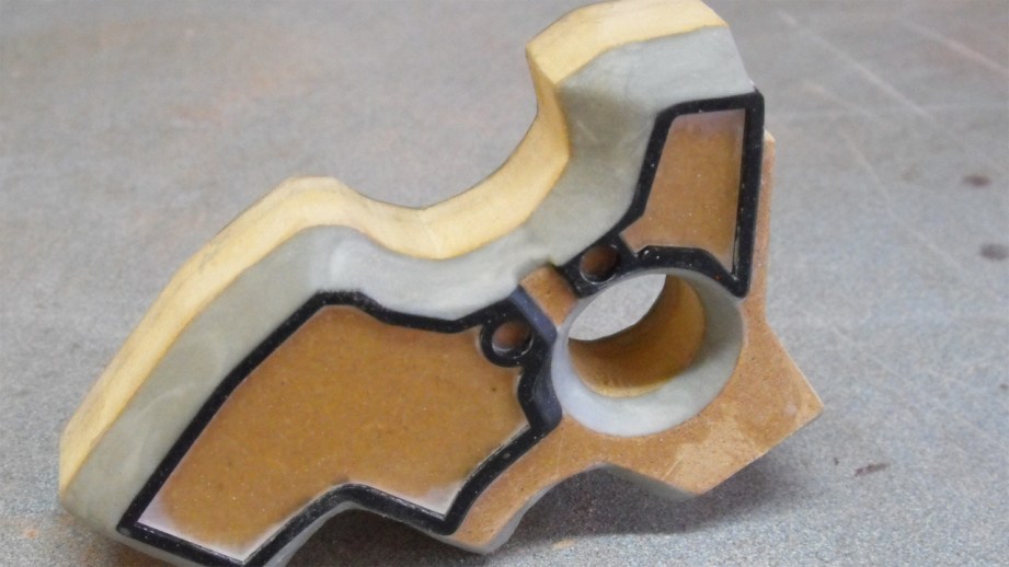
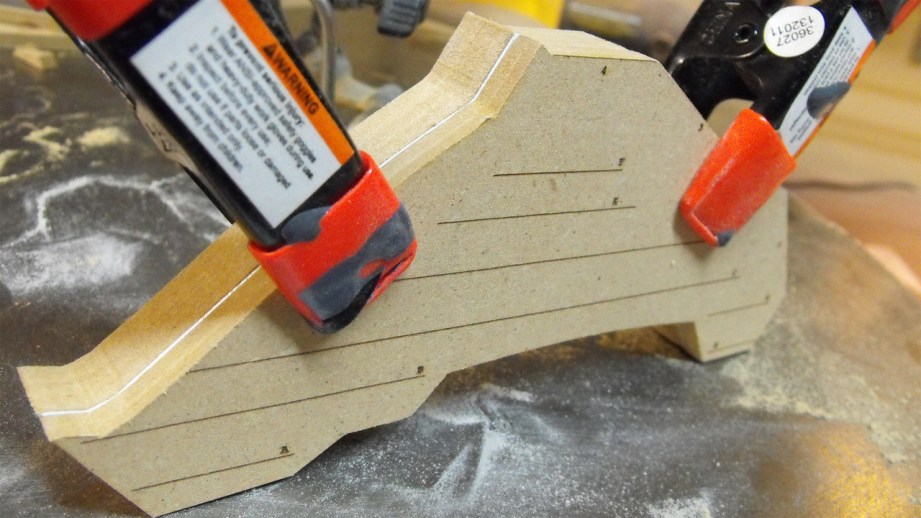
Not having any compound curves, the handle for the Needler was wrapped up in pretty short order. The center portion was made from laminated MDF sheets to be .75″ thick – matched to the scaled blueprints printed out before. Additional details on the side were added in .25″ MDF then accented with .118″ acrylic.
The side handles are supposed to have a slight indentation, so an additional insert was cut out of .080″ acrylic and inset into the grip texture. This gives the handle a very slight step, and the process is much easier than trying to trim out a flat plane like this by hand. Once everything was glued up, Apoxie Sculpt was used to fill in the beveled areas.
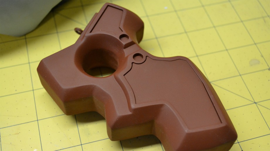
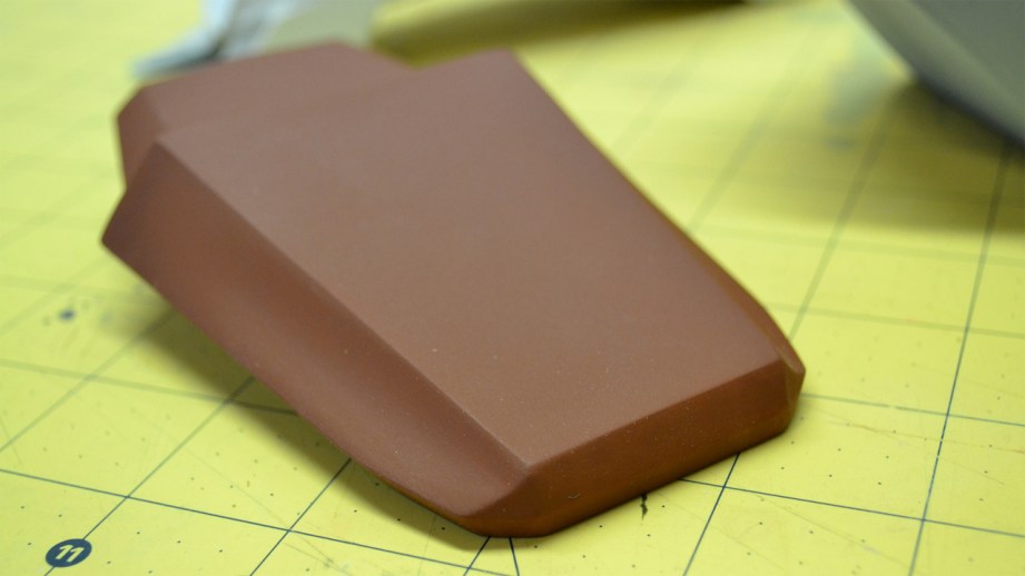
There’s a fair bit of sanding (you’re going to hear that a lot) between the above shot and this one below, but the handle is about 90% finished at this point. If you’re wondering why it looks like its cast in chocolate, thats the Krylon “Ruddy Brown” primer I’m partial to using. I’ve found it dried well even in the humidity here in GA and doesn’t clump up when sanded. Your mileage may vary, so make sure to test out and find the stuff that works best for you in your climate.
From the descriptions above you can kind of get a sense of how things are going to progress from here. This piece in the art file below is the sort of “barrel” portion where the needles would come out from the in-game model. Since there’s two of these mirrored around one axis on the actual gun, I’ll just be making one and molding it for its twin.
Framework starts out as layers of styrene and acrylic, with profiles drawn from the X, Y and Z perspectives. This gets skinned in layers of styrene for the flat parts and Apoxie Sculpt for the curved bevels. After a lot of sanding, the part is closing in on complete.
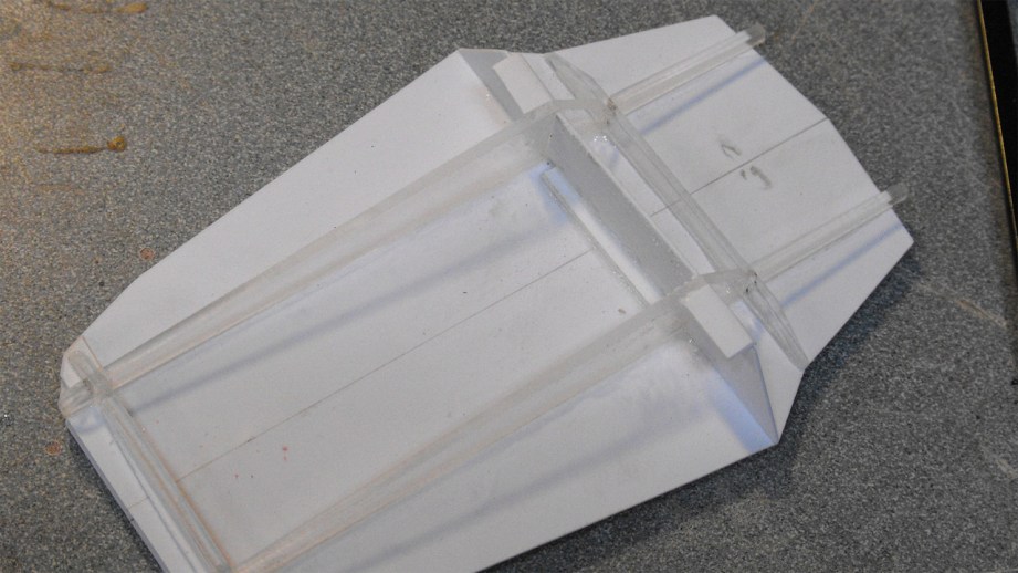
Now let’s take that one step further with the “emitter” part – the jaw-shaped piece that affixes to the front of the upper casing. This part has curved sides, but is otherwise a pretty straightforward beveled part. The center spine was cut from MDF parts, with lines etched into the sides for acrylic standoffs.
Disregarding the technicolor assortment of acrylic, these standoffs represent the curve of the outer edge of the emitter. Look at it from a top-down perspective, and I think you can see where I’m going with this.
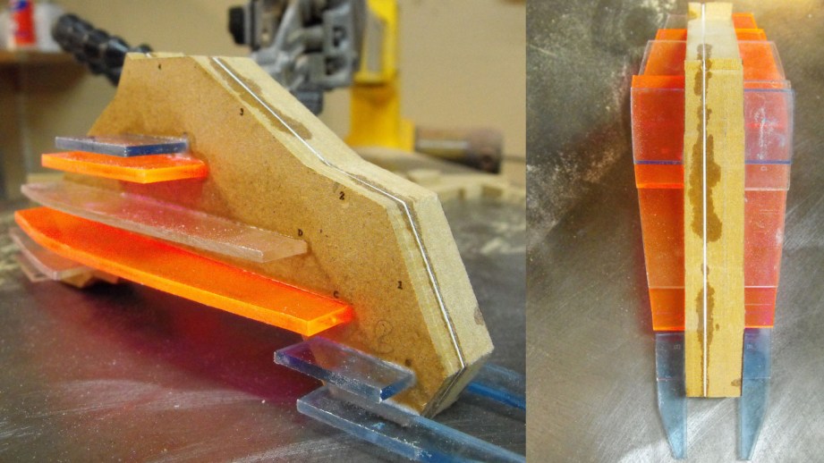
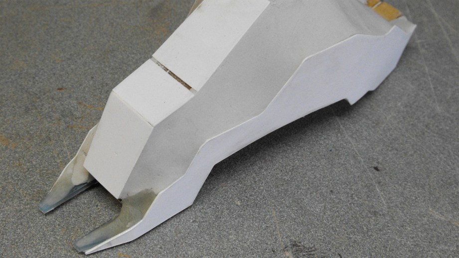
I used a sheet of .040″ thick styrene to skin the outside of these standoffs – this stuff is very flexible and while it wouldn’t be a good solution for something like the underside of the top casing where we need a nice flat edge, it’s ability to easily form a curve makes it perfect here. This piece isn’t finished just yet – the epoxy clay in the beveled sections need to be shaped and sanded a bit more – but the basic framework is complete. I just need to follow the lines and fill in the geometric shapes of the bevel and its complete.
While this seems like a lot of writing for just a few hunks of primer-tinted shop flotsam, I hope it does a good job of illustrating how I sculpt the basic shapes of a project. I’ll be continuing this trend with the rest of the parts of the gun since I’ve only got about half of it started thus far, and the next project installment will cover adding more detail and depth with panel lines and recessed areas in the base shapes.
See you again in two weeks!
The Volpin Project, Part 1: Introductions
The Volpin Project, Part 2: References and Blueprinting
The Volpin Project, Part 3: Selecting Materials


9 thoughts on “The Volpin Project, Part 4: Taking Shapes”
Leave a Reply
One Day Builds
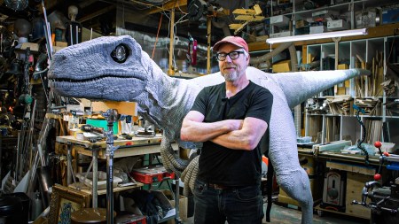
Adam Savage’s One Day Builds: Life-Size Velocirapt…
Adam embarks on one of his most ambitious builds yet: fulfil…

Show And Tell
Adam Savage’s King George Costume!
Adam recently completed a build of the royal St. Edwards cro…

All Eyes On Perserverance – This is Only a Test 58…
We get excited for the Perserverance rover Mars landing happening later today in this week's episode. Jeremy finally watches In and Of Itself, we get hyped for The Last of Us casting, and try to deciper the new Chevy Bolt announcements. Plus, Kishore gets a Pelaton and we wrack our brains around reverse engineering the source code to GTA …
One Day Builds
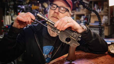
Mandalorian Blaster Prop Replica Kit Assembly!
Adam and Norm assemble a beautifully machined replica prop k…
House of MCU – This is Only a Test 586 – 2/11/21
The gang gets together to recap their favorite bits from this past weekend's Superb Owl, including the new camera tech used for the broadcast and the best chicken wing recipes. Kishore shares tips for streamlining your streaming services, and Will guests this week to dive into the mind-bending implications of the latest WandaVision episod…

One Day Builds
Adam Savage’s One Day Builds: Royal Crown of Engla…
One of the ways Adam has been getting through lockdown has b…
Making
Adam Savage Tests the AIR Active Filtration Helmet…
Adam unboxes and performs a quick test of this novel new hel…
Making
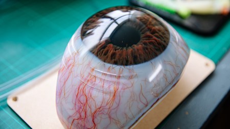
Weta Workshop’s 3D-Printed Giant Eyeballs!
When Adam visited Weta Workshop early last year, he stopped …
One Day Builds
Adam Savage’s One Day Builds: Wire Storage Solutio…
Adam tackles a shop shelf build that he's been putting off f…
Show And Tell
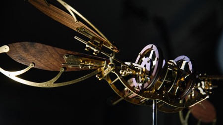
Mechanical Dragonfly Automata Kit Build and Review
Time for a model kit build! This steampunk-inspired mechanic…
You mention the little “aha” moment with photoshop, I am getting those moment with each post we get. Seeing this process is really cool. The project is looking great!
Very inspiring to see the build progress, makes me want to glue my fingers together.
B-E-A-utifuly not sure if thats a word but am going with it
A-ha moments are the best, aren’t they? 🙂
wow this is really interesting, I love this type of stuff on the site
Isn’t that what he covered in Part 3?
It sure is coming together.
This honestly makes this seem a lot more possible for me to even attempt something like this. I have decent 3D sculpting and modeling abilities and it would be really cool to create my own stuff using this process. Thanks!
That gif is epic