


Bits to Atoms: Making a MintyBoost USB Charger
One of Adafruit's best kits is the MintyBoost USB charger which you solder together yourself, runs off of two AA batteries and fits in an Altoids mint tin. But I wanted to make my own enclosure that solved some of its problems.
[Norm’s note: Every other week, 3D printing expert (and Inventern competition champion!) Sean Charlesworth will share some of his insight and experience of 3D design and printing. He started last month discussing modern 3D printing technologies, and will alternate between those guides and walkthroughs of his past print projects to show applications of those tips. Here’s the first project walkthrough.]
I am a huge fan of Adafruit Industries, which was founded right here in NYC by MIT engineer, Limor ‘Ladyada’ Fried and is a supplier of great DIY electronics projects and an excellent source of information. Adafruit hand-picks quality electronic components, designs their own boards and kits and has an amazing tutorial section. I am no electronics wiz and have managed to put together some pretty cool stuff with their guidance. I love this place.
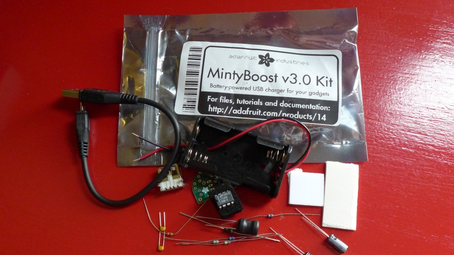
One of Adafruit’s first kits was the MintyBoost USB charger which you solder together yourself, runs off of two AA batteries and fits in an Altoids mint tin. Throw one in your bag and they are super handy when you need an emergency phone charge. It’s worth the looks you get when plugging your phone into an Altoids tin. I’ve built five of these and from those builds thought of two improvements I wanted to make. The first problem was if the batteries were left in for an extended period of time they would eventually discharge to the point that they would leak and I killed two MintyBoosts this way. The second thing I wanted was enough room in the case to fit a small charge cable, so I decided to design and 3D print my own enclosure.
Today I’m going to show you how I approached this project and printed this custom MintyBoost charge pack.
I’ve Got a Plan
To solve the battery meltdown problem, I decided to install a switch to completely cut power when not in use. I found a small switch at RadioShack (yes, some still have electronics parts) and the perfect short USB cable from Newegg. With these in hand, the first task was to build stand-ins for the all the parts so I could layout the box. I measured everything with calipers and used simple shapes to represent the greenboard, batteries, switch and cable and screws. I could shuffle these around to determine the best layout.
3D Modeling: An Expected Journey
For almost all of my projects including the Octopod, I have been using Cinema 4D, an alternative to the very popular Maya. Both are polygon modelers typically used for animation, visual effects, motion graphics, and video game assets. My introduction to modeling and animation was with Maya, an industry standard but I kind of hate it. One of my professors, an industry pro, would say, “Maya defaults to broken.” I find it overly complicated and a chore to use but it can also do amazing things and a lot of studios have workflows built around it. Cinema 4D is a German program, seems to be very popular overseas and is used often for motion graphics (flying logos, intros and outros to programs, etc) in the States. It has seen heavy use in films such as Iron Man 3 and Serenity but is still not as popular as Maya. I just prefer the interface, structure, how it works and particularly the modeling tools, so I’ve stuck with it but this is just one newbie’s opinion.
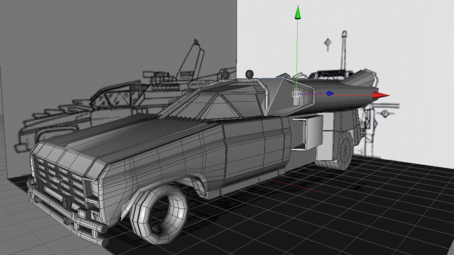
Cinema now allows you to model with real measurements vs generic units so I tend to work in metric any time I can because it makes things so much easier. (Why can’t we get on board with this?) When polygon modeling, I will look at the object I want to make and break it down into simple shapes to figure out the best way to tackle it. For example, when I built the Buckaroo Banzai Jet Car, I blocked it out with primitive shapes that are supplied in the program and kept refining them and adding detail to arrive at the finished product.
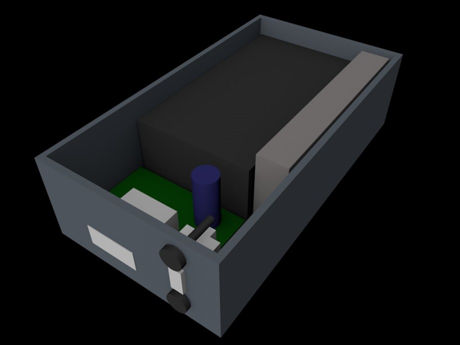
Modeling the MintyBoost box was pretty straightforward; I roughed it out with a cube and…turned it into a box. The trick was to figure out the best way to add details and the tolerances needed to fit the switch and other components. Check out the video in which I demonstrate ways to model the box.
The Print: There and Back Again
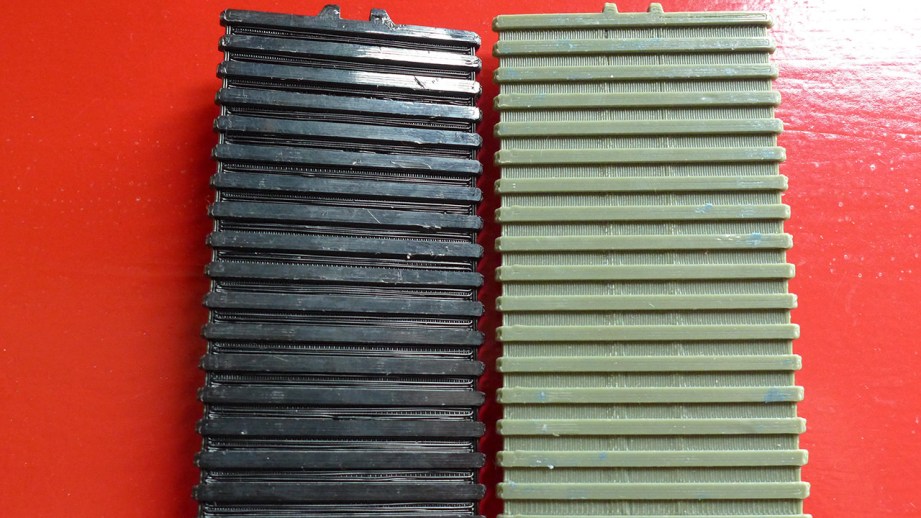
So after modeling a rough version of the box using my stand-ins I wanted to print a quick prototype on the MakerBot. When printing with FFF you can control the quality and speed of the print a few different ways. You can change the layer height which determines resolution, specify how thick the outer wall should be, designated by ‘shells‘ and how solid the item should be by the percentage of fill.
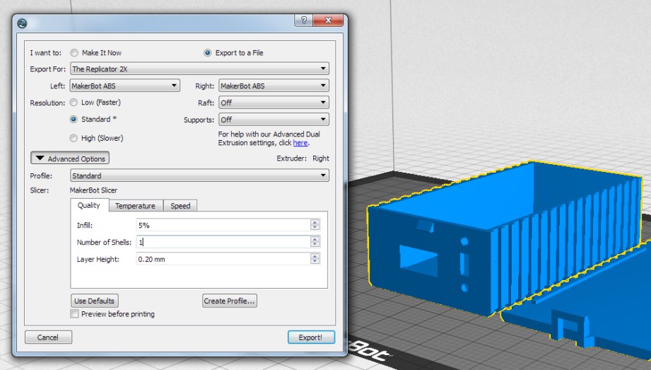
The ‘default’ resolution for most FFF printers is currently .2mm (or 200 microns) and .1mm for ‘fine’ prints, I generally use .2mm for my prints including rough drafts. Shells will change the thickness of the outer wall by ‘drawing’ the outer shape for each shell you designate. More shells will make your object stronger but too many shells can cause problems when printing small items or intricate detail. My MintyBoost box has very thin walls so it’s better to do 1 shell with fill rather than 2 shells. The wall thickness is so small that 2 shells would take up most of the area, leaving no space for fill which would result in gaps on the top of the print.
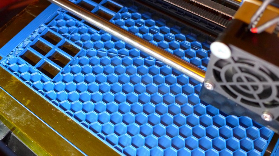
Finally, the higher the fill the longer it takes to print but it will also be stronger. If you specify anything below 100%, the slicing program will typically use a honeycomb pattern to meet your fill %. I should also mention that the actual speed of the print can also be set. This is simply how fast the print head moves while printing. Most decent printers can handle 90 – 150 mm/s travel speed and use acceleration algorithms to help make nice prints. In comparison, my unmodified Thing-O-Matic couldn’t go much past 20 mm/s without making crappy prints.
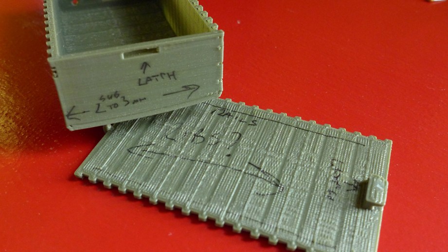
For the rough box I used .2mm layer height, 1 shell and 0% fill. This produced a flimsy box that printed very fast but since I just needed to know if everything would fit inside, strength didn’t matter. I’ll often write the print specs and other redesign notes right on the prototype so I know exactly how it was printed. At this point I might change the position of component openings, the size of the box, etc. and then do another test print.
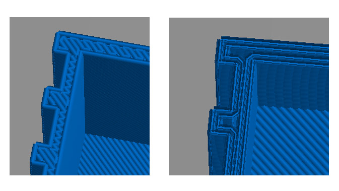
Once I was happy with the layout I added a simple latch and rails on the lid to keep it from shifting. I jazzed up the box with some fins which made it more challenging to print and is a good example of how 3D printing can be fiddly. Due to the design of the lid, it has to print top-down, meaning the fins will be the first thing to print. This also means that the gaps between the fins will have nothing to hold them up while printing which is called bridging. With FFF you can usually bridge small distances but the first time I printed the lid, the slicing program printed everything parallel to the fins so there was nothing to hold up the recessed areas and it got messy. I had to rotate the part in the slicing program so that it would print perpendicular to the fins and produce a better print.
A Charged Phone for All
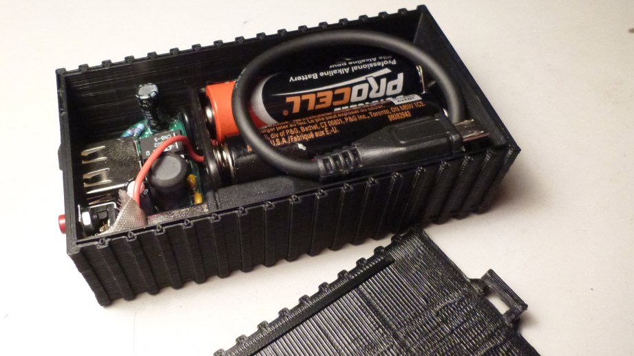
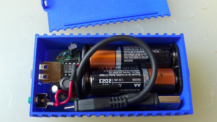
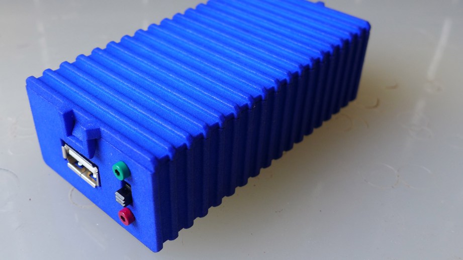
For the final print I used a higher infill for strength and everything fit in as expected. The switch was a bit of a pain to install and should be done before putting any of the other components in. I love having the cable as part of the package and the switch has allowed me to keep batteries installed indefinitely. I liked it so much that I decided to get a print done at Shapeways in the strong and flexible material. I also had it polished which takes off the rough edges for a nicer finish (this can lose fine detail on intricate pieces). I’m really pleased with the print and carry it in my bag all the time.
I hope you’ve enjoyed the MintyBoost walkthrough, post any questions in the comments and I will try to answer them all. If you have your own printer, the files for the MintyBoost Box can be downloaded from my Thingiverse page. The part numbers for the switch and cable are included and there’s a link for the Shapeways version if you would like one but don’t have a printer.
All photos and images courtesy Sean Charlesworth


12 thoughts on “Bits to Atoms: Making a MintyBoost USB Charger”
Leave a Reply
One Day Builds
Adam Savage’s One Day Builds: Life-Size Velocirapt…
Adam embarks on one of his most ambitious builds yet: fulfil…

Show And Tell
Adam Savage’s King George Costume!
Adam recently completed a build of the royal St. Edwards cro…

All Eyes On Perserverance – This is Only a Test 58…
We get excited for the Perserverance rover Mars landing happening later today in this week's episode. Jeremy finally watches In and Of Itself, we get hyped for The Last of Us casting, and try to deciper the new Chevy Bolt announcements. Plus, Kishore gets a Pelaton and we wrack our brains around reverse engineering the source code to GTA …
One Day Builds
Mandalorian Blaster Prop Replica Kit Assembly!
Adam and Norm assemble a beautifully machined replica prop k…
House of MCU – This is Only a Test 586 – 2/11/21
The gang gets together to recap their favorite bits from this past weekend's Superb Owl, including the new camera tech used for the broadcast and the best chicken wing recipes. Kishore shares tips for streamlining your streaming services, and Will guests this week to dive into the mind-bending implications of the latest WandaVision episod…

One Day Builds
Adam Savage’s One Day Builds: Royal Crown of Engla…
One of the ways Adam has been getting through lockdown has b…
Making
Adam Savage Tests the AIR Active Filtration Helmet…
Adam unboxes and performs a quick test of this novel new hel…
Making
Weta Workshop’s 3D-Printed Giant Eyeballs!
When Adam visited Weta Workshop early last year, he stopped …
One Day Builds
Adam Savage’s One Day Builds: Wire Storage Solutio…
Adam tackles a shop shelf build that he's been putting off f…
Show And Tell
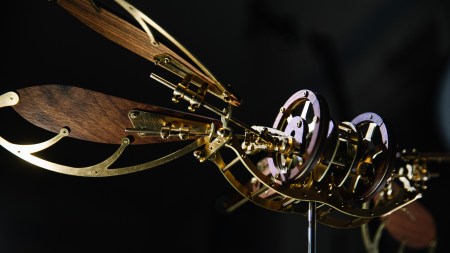
Mechanical Dragonfly Automata Kit Build and Review
Time for a model kit build! This steampunk-inspired mechanic…
Would using Eneloops give more or less battery life than Alkalines?
An alternative to stuffing the USB cable inside would be to have a slot on the outside you can snap it into so you can just pluck it out and start charging without the need to open the lid and plug it in.
Well done.
Not sure, probably about the same. Lithium would give you a nice boost.
I like that idea. While this does exactly what I wanted, it is a tad bulkier than I would like.
This is a great article/tutorial. An entry level project, very clearly explained and pretty much start-to-finish. I think a lot of readers have been wanting this type of content for a while. 🙂
Would this kind of “simpler” modeling work in SketchUp.
Great to see how Cinema is working.
For the most part. I have used SketchUp and other ‘basic’ programs and there’s a lot you can do and they tend to be more intuitive for beginners but then you get to a certain part you want to build and the features to do it easily and well aren’t there. I’ll cover software down the road.
Excellent. I come across a huge variety of softwares in my profession and it is always interesting to see applications.
Nice build documentation. I’ve also made several mintyboost kits in the past. I’ve recently been making them with small lipo packs instead of the AA packs, it makes for a much smaller/lighter build. I’ve used the adafruit pushbutton power switch as well, which makes for a nice flush finished product with indicator light. I put a hole in the 3d print and have the head of the button in there and just barely recessed so you can push it with a finger. The led diffuses through the print nicely as well.
For software, I use openscad because I like being able to type to move things around since I’m much faster typing instead of mousing/touchpadding in the GUI. Though I’d like to start using autocad inventor to be able to easily make and use subassemblies and model their motion in relation to other items in a model.
I think software tools are just like regular tools, i.e. hammers and screwdrivers, you should use the best tool for the job. I do a lot of very large woodworking projects, and Sketchup is ideal for these projects. I am finishing up a room-scale, stand-alone loft with build-in shelves and stairs. It was dirt simple with Sketchup. However, I agree with Countspatula that for his tasks other tools are much better.
Countspatula, unfortunately the tools you mention are expensive so it is worth the time to research them. I hope you cover software soon. I would love to at least know what all the choices are.
I really like their lipo packs and charge boards, using them for an Iron Man Arc Reactor. I thought about using them for the MintyBoost but still like the fact that you can pick up AA anywhere. You should post of pict of your charger, sounds cool.
I spent most of High School programing, including Logo where you’d have to enter line commands to draw things (forward 40, right 90, forward 40, left 45. Craziness) but OpenSCAD just doesn’t click with my brain. But everyone has what works for them. Along those lines it’s worth noting LDraw and MLCAD which were community developed LEGO CAD programs way before the official Digital Designer. Folks in the community volunteer to ‘build’ parts by entering code to describe the part, much like OpenSCAD (might even be based on OpenSCAD, don’t know)
I totally agree. A lot of what I have been making would probably be better suited for CAD and I just picked up SolidWorks but now need the time to use it. Sometimes going with what you know and making it work can be less time-consuming than learning something new. My least favorite thing about digital design is keeping up with all the software.
Wonderful and waiting on.