


How To Make a Handheld Camera Gimbal Mount
There's no question that motorized gimbals do a fabulous job of hiding the bumps and bobbles when you're using an action camera. Here's how I assembled my own handheld gimbal mount.
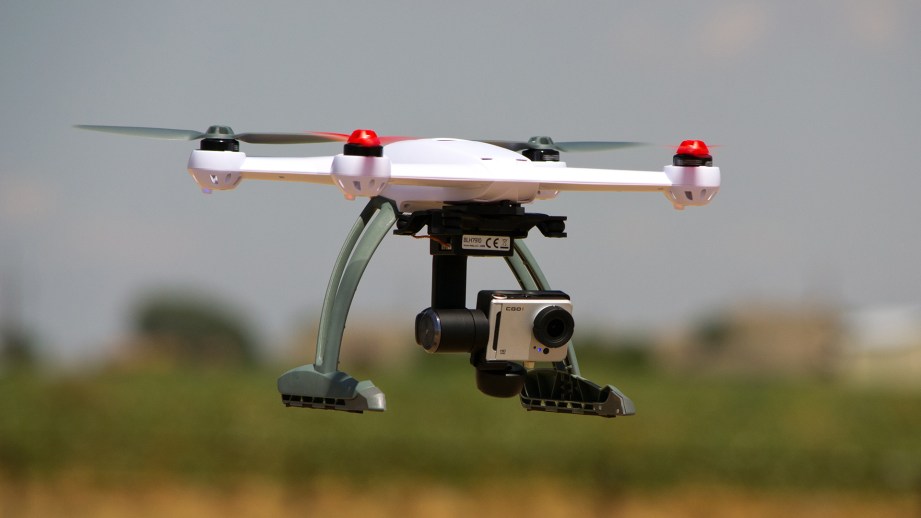
There’s no question that motorized gimbals do a fabulous job of hiding the bumps and bobbles when you’re using an action camera. They’re pretty much required equipment for multi-rotor flyers who want to capture decent footage from on high. Recent reviews of the DJI Inspire 1 Mount and the Feiyu-Tech G3 Ultra convinced me that I needed a gimbal for my ground-based video shoots as well.
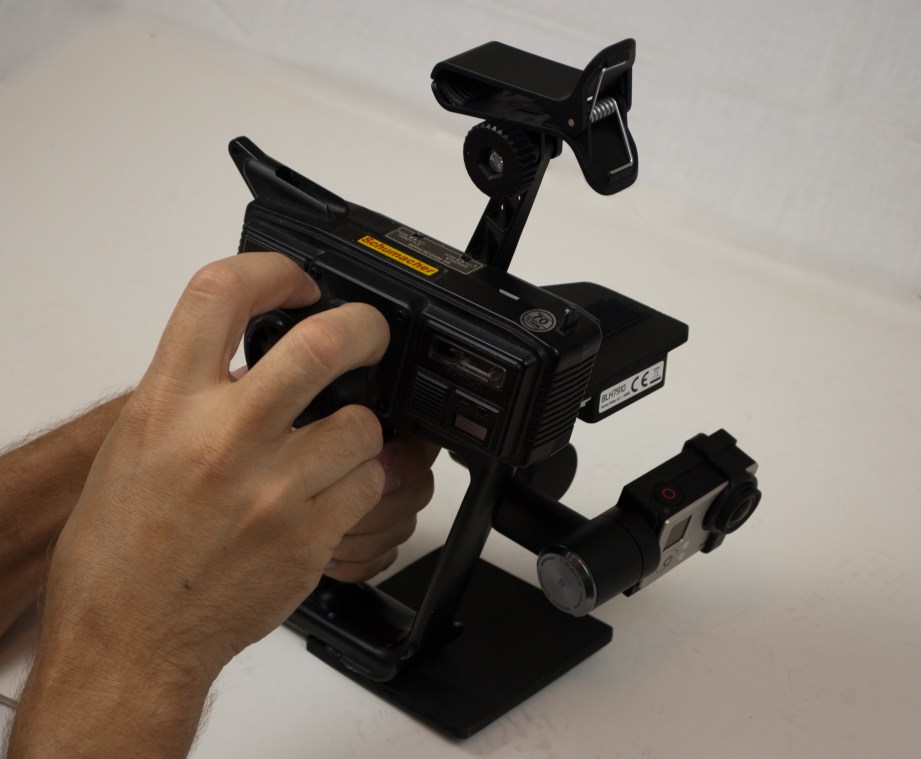
As I was browsing the selection of handheld gimbals, I ran across the Yuneec Steady Grip. Like the Inspire 1 Mount, the Steady Grip merely provides an alternate method to hold, power, and control a gimbal that would otherwise reside on a multi-rotor. The unique pistol-like form factor of the Steady Grip made me realize that I already had most of the parts that I needed to build my own handheld gimbal mount. So I abandoned the store-bought approach and went D-I-Y.
Gathering Parts
My prime motivation for this project was the desire to easily swap one of my gimbals between its aerial mount and the handheld mount. Being able to utilize a gimbal I already owned presented a substantial cost savings. Adding a gimbal to the bill of materials for this project would likely make it more expensive than just buying a handheld gimbal system outright.
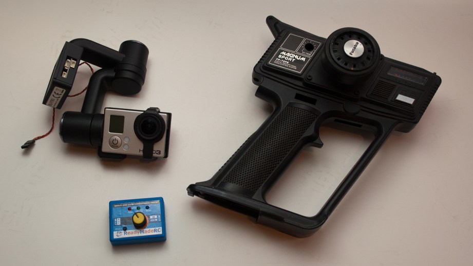
I chose to use the GB200 2-axis gimbal from my Blade 350QX2 quad. The entire gimbal assembly can easily be removed from its mount on the quad by lifting a lock tab and sliding the base off of its rails. I had already upgraded the gimbal with the proper frame to hold a GoPro Hero 3 camera.
To emulate the style of the Steady Grip, I plundered my stash of old RC systems. Among them are several pistol-grip transmitters that I haven’t used in years. I located a well-used Futaba Magnum Sport that looked like it would do the trick. It didn’t matter that the electronics of the radio were still in good shape. I really only needed the plastic shell. Finding a new use for one of my squirreled-away “treasures” has certainly done nothing to improve my hoarding tendencies!
I wanted to be able to control the pitch of the gimbal while it is in the hand mount. On the quad, this function is controlled by a channel of the radio. I used a servo driver (also called a “servo tester”) to transfer this capability to the hand mount. I’ll explain later just how that works.
Different gimbals may require a wide variety of input voltages to operate. I wanted to be sure that I provided the correct voltage for the GB200, but I could not find any specs that defined what it should be. I measured the voltage output at the gimbal power pins on the Blade 350 at around 4.3 volts. With that value in hand, I felt comfortable buying a 5 volt voltage regulator for the hand mount.
As with most of my projects, I didn’t begin with a firm vision of the final product. This design was fluid right up until the last screw was tightened. To get started, I placed the basic parts before me and mentally explored the different options. Vanity usually takes a back seat to my desire for simplicity and functionality. Even though the simplest solution to a problem is quite often the best approach, it isn’t necessarily the most obvious. In fact, sometimes identifying and removing the superfluous stuff is the hardest part. I think that this project ended up sufficiently rudimentary.
Putting It Together – Wires First
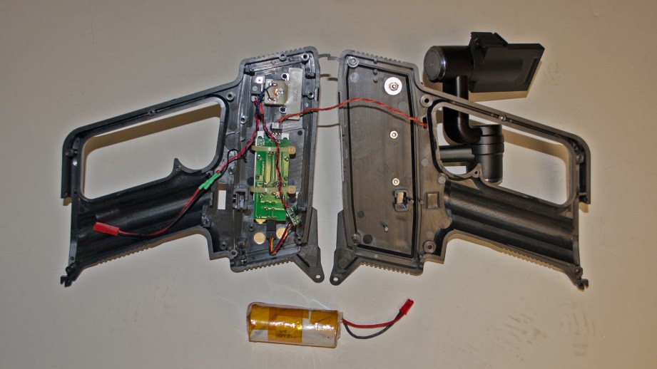
I decided to tackle the electronic side of the project first. I began by gutting the components from the transmitter case. My plan was to just rip everything out, but I realized that I could recycle the power switch and voltage indicator rather easily. So those parts stayed in place
Next, I configured the servo driver. A servo driver is a device that allows you to operate a servo, ESC or other RC device without a radio system. It works by emulating the PWM (Pulse Width Modulation) signal that the device would normally receive when hooked to a radio receiver. You simply connect a 5 volt power source and the device to the servo driver. A potentiometer on the face of the servo driver allows you to articulate the device through its full range of motion. It’s a very handy and inexpensive tool to have in your workshop.
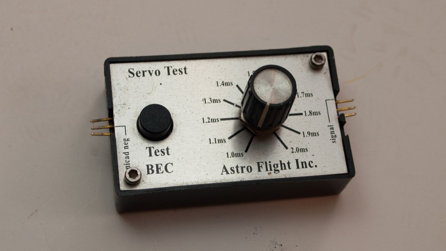
I purchased a $5 servo driver from Ready Made RC (RMRC) with the intent of permanently installing it in the hand gimbal mount and using it to provide pitch control. After some fiddling, I decided that I liked my new servo driver more than the Astro Flight model I’ve been using for over 10 years. My old one still works just fine, but the RMRC unit has a button that moves the device to the exact center of its travel range – a function I will use frequently. So I decided to keep the RMRC unit for my workshop and install the Astro Flight unit in the gimbal mount.
I connected the small plug of the GB200’s 3-wire harness to port C of the gimbal. This is the same plug configuration used with the quad, so you’ll want to buy or make a second harness to avoid having to move this part with every swap. The receiver plug of the harness was mated to the output side of the servo driver. With a 4-cell NiCad battery for power (just for this test), I performed a quick check to ensure that the servo driver would work with the gimbal as planned…it did. I removed the circuit board of the servo driver from its case and examined ways to mount it inside the transmitter body.
Using a combination of scrap plastic and zip ties, I was able to mount the servo driver board quite easily. Best of all, I located it such that the steering wheel of the transmitter connected to the output shaft of the potentiometer. This allows me to control the pitch of the gimbal by turning the steering wheel.
Anyone else attempting a similar project will likely be using a different transmitter case and servo driver. So the specifics of how I mated the potentiometer to the steering wheel are probably irrelevant. In short, I drilled an axial hole in the shaft of the steering wheel that matches the outer diameter of the potentiometer output shaft. The two parts are a relatively loose slip fit when pressed together. I could have glued or taped them together, but it isn’t necessary. I then mounted the servo driver board such that all of the parts are somewhat aligned (it isn’t perfect).
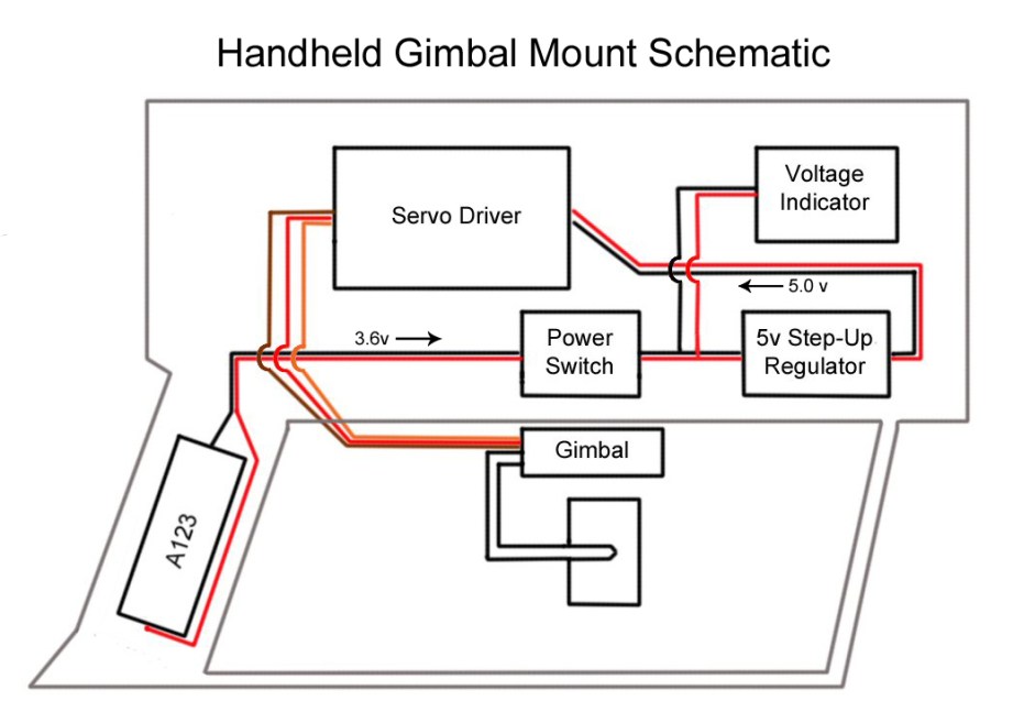
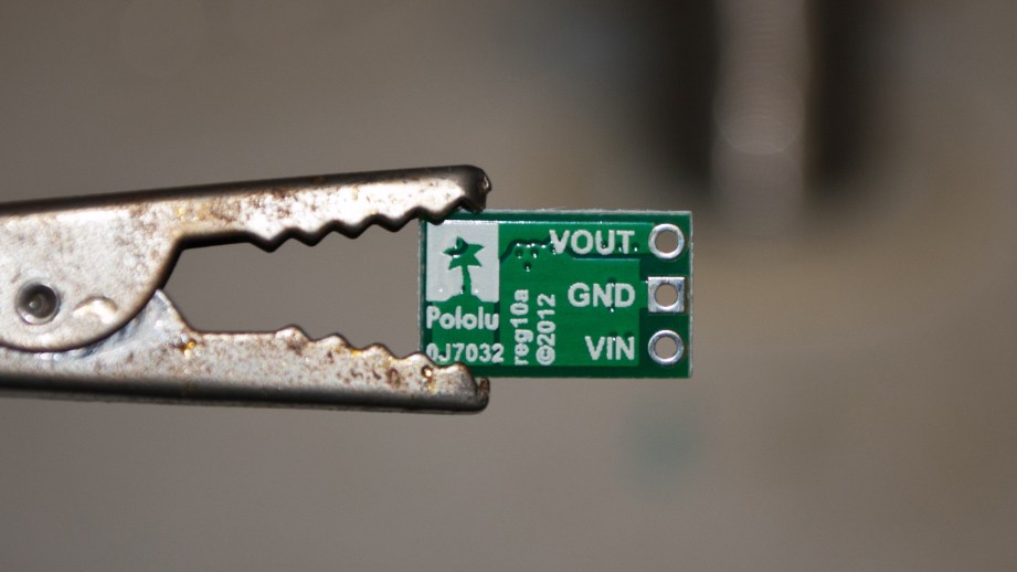
I have a lot of loose A123 Lithium Nanophosphate cells that I like to use for different projects. These cells are 3.6 volts when fully charged, so I was planning to use two cells in series (7.2v) with the aforementioned voltage regulator to knock down the system voltage to 5 volts. That plan changed when I came across a 5-volt “step-up” voltage regulator. Rather than throwing excess voltage overboard, this regulator takes a lower voltage input (as low as 2.5v) and pumps it up to 5v at the cost of increased current flow. Choosing this regulator allowed me to use a single A123 2300mAh cell.
The single A123 cell is a nice rattle-free fit in the original battery location inside the handle of the transmitter. I soldered a short lead with a JST power connector to the A123 cell. I also soldered the mating connector to wires leading to the stock power switch of the transmitter. I then connected wires from the output side of the switch to the input side of the voltage regulator. The output side of the voltage regulator received a standard servo plug that connects to the power port of the servo driver.
I also soldered jumpers from the output side of the power switch to the analog voltage indicator. It doesn’t indicate actual voltage, but rather a 0-100 scale, with 100 being fully charged. Knowing that the transmitter originally used batteries up to 12 volts, I figured that I would just have to recalibrate how I read the meter with my 3.6 volt input. I guess that the meter wasn’t reading raw input voltage from the battery because even 3.6 volts pegs it at 100. I’ll keep an eye on it as this battery depletes and determine if the meter will be useful at all.
Mounting the Gimbal
After lots of chin scratching, I decided that placing the gimbal on the left side of the transmitter case offered the most compact footprint. The first order of business was to cut off, sand, or otherwise flatten any protrusions in that area of the transmitter. I then bolted a 3.5″ length of aluminum angle stock in place. To this I attached a shelf made of ¼” plywood. I originally made the shelf of 1/8″ Kydex plastic, but it was too flexible.
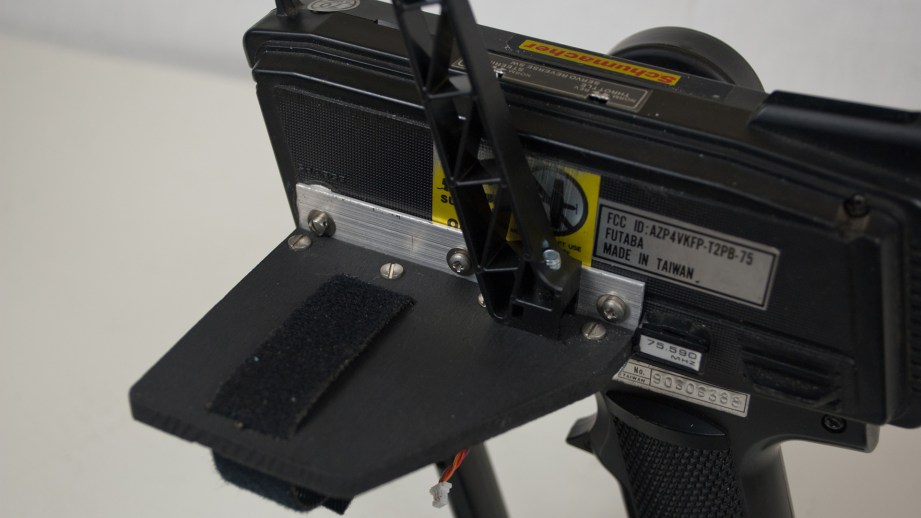
A 2-sided Velcro strap is used to hold the gimbal to the shelf. I cut slots in the plywood that allowed me to loop the Velcro around the base of the gimbal. A small patch of adhesive Velcro on the bottom of the gimbal base prevents it from sliding under the strap. I also added strips of self-adhesive felt to the bottom side of the shelf to make the interface with the gimbal a little cushier. The final mount is surprisingly rigid, but the gimbal can be removed in a matter of seconds. So swaps between the quad and the handheld mount are easy.
I also wanted to add a clamp to hold my phone. Once again, I was able to borrow the needed part from my Blade 350QX2. This time, I pulled the phone clamp from the transmitter, which is fastened with a single screw. I drilled a .25″ diameter hole through the shelf and angle stock. Then I screwed the mount into place. Although I did have to source a longer 5mm diameter screw from my hardware stash.
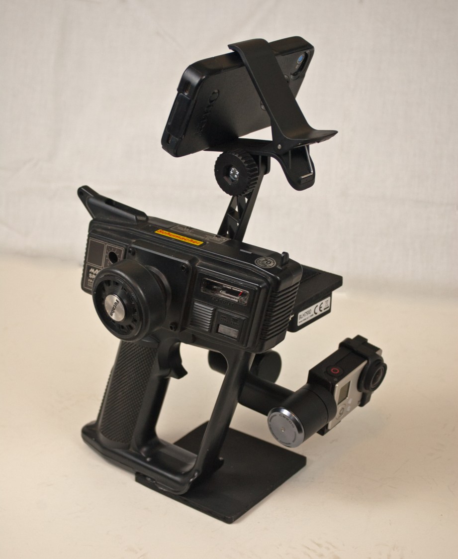
The final assembly step was to add a base so that the gimbal mount could stand on its own. I cut a 4″x4″ plate of ¼” plywood and attached it to the bottom of the radio, being careful to leave the battery hatch unobstructed. The plate is secured using a combination of GOOP adhesive and self-tapping, flat head screws (I countersunk the screw holes).
Using the Gimbal Mount
My initial testing of the handheld gimbal mount has been encouraging. It definitely helps to smooth out the shakiness that is inherent when using a GoPro in your hand. This is especially evident when walking. My previous footage had significant bobbles each time my foot hit the ground. Now walking footage is much smoother. While not quite bounce-free, it’s definitely better. Perhaps I should learn to walk more stealthily when filming.
The balance of the unit isn’t bad. It is just a touch front heavy, so I don’t think it would ever cause a hand/wrist fatigue issue. The main problem I’ve encountered when using the hand mount is the latency of the Wi-Fi signal from my Hero 3 Black. Even though the camera and my phone are only inches apart, there is a 3-4 second delay with the image on my screen. I’ll have to look into solutions for that.
Another potential issue concerns the relative size of the handheld mount. Even when the gimbal is not installed, it’s much too large to fit into my camera bag. Short of strapping it to the outside of the bag, there may not be many transport options. That isn’t an issue for most of the filming I do, but I may have to keep the handheld mount at home during family vacations where space is limited.
Conclusion
Time will tell if this DIY design is practical enough to become my permanent non-flying gimbal mount. It has already provided an upgrade to my ground based GoPro footage. I’ll be using it a lot this summer to determine its strengths and weaknesses.
Even if I ultimately retire this gimbal mount, I only spent about $10 in new parts (servo driver and voltage regulator) to get it together. Most importantly, it was fun to envision this project and see it come together successfully.
Terry spent 15 years as an engineer at the Johnson Space Center. He is now a freelance writer living in Lubbock, Texas. Visit his website at TerryDunn.org and follow Terry on Twitter: @weirdflight


3 thoughts on “How To Make a Handheld Camera Gimbal Mount”
Leave a Reply

One Day Builds
Adam Savage’s One Day Builds: Life-Size Velocirapt…
Adam embarks on one of his most ambitious builds yet: fulfil…

Show And Tell
Adam Savage’s King George Costume!
Adam recently completed a build of the royal St. Edwards cro…

All Eyes On Perserverance – This is Only a Test 58…
We get excited for the Perserverance rover Mars landing happening later today in this week's episode. Jeremy finally watches In and Of Itself, we get hyped for The Last of Us casting, and try to deciper the new Chevy Bolt announcements. Plus, Kishore gets a Pelaton and we wrack our brains around reverse engineering the source code to GTA …

One Day Builds
Mandalorian Blaster Prop Replica Kit Assembly!
Adam and Norm assemble a beautifully machined replica prop k…
House of MCU – This is Only a Test 586 – 2/11/21
The gang gets together to recap their favorite bits from this past weekend's Superb Owl, including the new camera tech used for the broadcast and the best chicken wing recipes. Kishore shares tips for streamlining your streaming services, and Will guests this week to dive into the mind-bending implications of the latest WandaVision episod…

One Day Builds
Adam Savage’s One Day Builds: Royal Crown of Engla…
One of the ways Adam has been getting through lockdown has b…

Making
Adam Savage Tests the AIR Active Filtration Helmet…
Adam unboxes and performs a quick test of this novel new hel…

Making
Weta Workshop’s 3D-Printed Giant Eyeballs!
When Adam visited Weta Workshop early last year, he stopped …
One Day Builds
Adam Savage’s One Day Builds: Wire Storage Solutio…
Adam tackles a shop shelf build that he's been putting off f…
Show And Tell
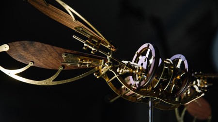
Mechanical Dragonfly Automata Kit Build and Review
Time for a model kit build! This steampunk-inspired mechanic…
Now that is a awesome money save will brilliant results. Very nice and great project!
I have that same Futaba transmitter back from my old RC10 days 🙂
I agree with you