


Bits to Atoms: 3D Modeling Best Practices for 3D Printing
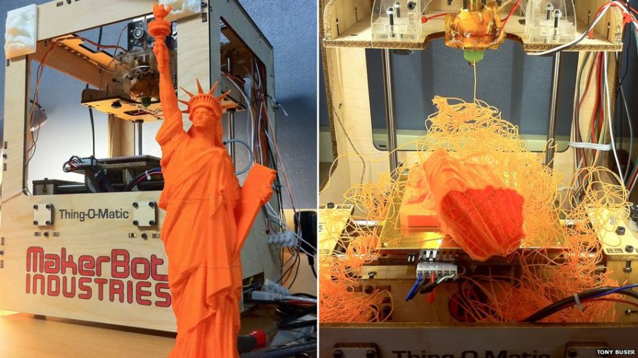
So you've managed to build your first 3D creation using modeling software. You send it to the printer and it comes out looking like something sent through a cosmic spatial anomaly. What the heck happened?
So you’ve managed to build your first 3D creation using modeling software. You send it to the printer and it comes out looking like something sent through a cosmic spatial anomaly. What the heck happened? Building your model on the computer is just the first step to ensure a proper 3D print. Today, we’ll go over best practices for modeling and how to prep those models for a good print.
Neatness Counts
Taking the time to sculpt a neat, clean computer model will prevent headaches down the road. This is particularly true of polygon models where deleting an edge, face, or vertex can quickly make a model unprintable. Using boole operations (adding and subtracting part together) is often used while building models, but can lead to messy models since two pieces of geometry are being combined or subtracted from one another.
Sloppy modeling can easily occur just in the process of figuring out how to build something. I will often build a quick, rough model to work through the layout, what parts need to be made, and how to build them. I will rebuild the whole thing as a much cleaner model based on the rough version. One of the best pieces of advice I got from my modeling mentor is, ‘don’t be afraid to rebuild something‘. It sounds like a drag but rebuilding a model from scratch always goes quicker than the original and it will be a cleaner model, using what was learned from the first version.
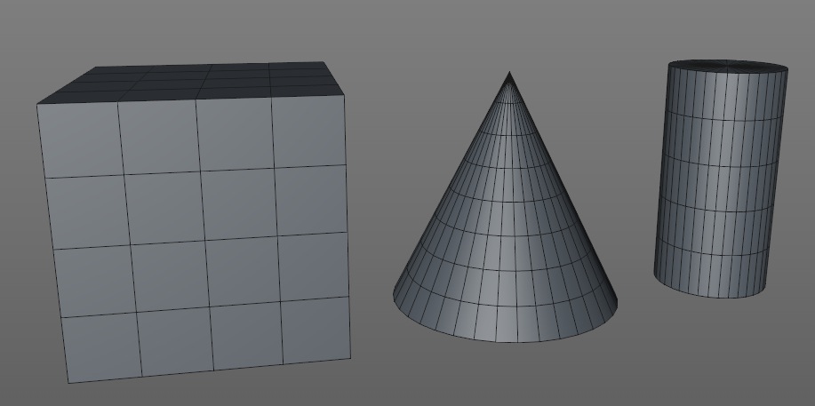
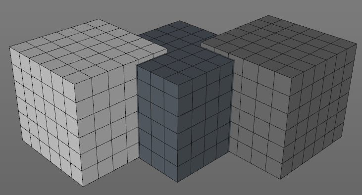
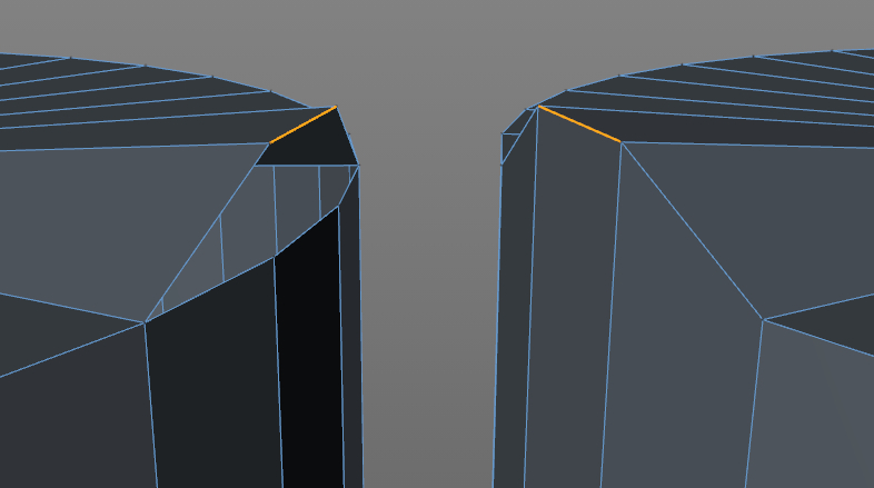
If modeling with polygons, it’s in your interest to keep the mesh in quads (each face is four-sided) and avoid “n-gons” (in modeling, any polygon that is not 4-sided). Modeling with quads makes adjusting the model much easier, whereas n-gons will kind of mess things up. In general, any modeling program will make it easy to model in quads since any primitive (cube, sphere, cone, torus, etc) created will automatically be made out of quads.
A good housekeeping rule it to name everything upon creation. If there’s ten different cubes that were used to make ten different parts on your model it will be tough to tell them apart if they’re all listed as ‘cube’.
Size Matters, Somewhat
Due to limitations of both the printer and material used, you must pay constant attention to wall thickness, size of details and overall size of the print.
Due to limitations of both the printer and material used, you must pay constant attention to wall thickness, size of details and overall size of the print. If you make a wall too thin or detail too small you will most likely have some holes and breakage on the printed model. This can be tricky considering that not all modeling programs let you build in a particular unit. Some programs may list a circle as being 10 in diameter, but what is the unit of measurement? That’s the glory of digital design; it doesn’t really matter since the model can be scaled up and down almost indefinitely. But if the material you are printing in needs a minimum wall thickness of 1mm, then units become important.
In this case, I will generally decide that 1 unit = 1 cm or 1 inch, etc and model accordingly. Even having done this, you may export the STL and rather than 10 cm long your model is 100 cm long! It all depends on how your program exports, some will allow you to specify the units, some won’t. Regardless, once the STL is opened in the slicing program you should be able to scale it to the correct size.
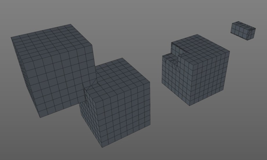
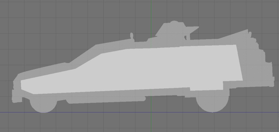
A helpful trick is to create a reference cube to ensure proper scaling. If I decide to model in centimeters I create a 5 x 5 x 5 unit cube and subdivide it 5 times and know that the cube should be 5 cm when printed and each subdivision is 1 cm. During construction I will use the cube to verify distances that might otherwise be hard to measure. When exporting the finished model I will export the cube as a separate object and then bring them both into the slicing program. I can select the cube and easily see if it’s the correct size and scale the cube and model up and down as needed. When done, the cube is deleted and the main model should be at the proper scale.
Subdivide and Conquer
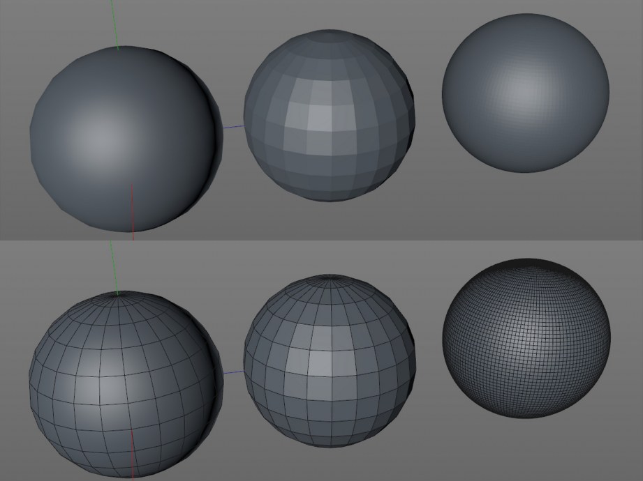
As we have discussed before, 3D printers only print pure geometry, so you need to make sure your model is smooth enough to print well. If you are using a polygon modeler remember to turn off any rendering shaders since they fake smoothness on the screen.
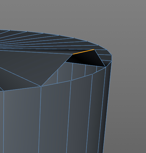
If your model looks chunky on-screen you will need to add more subdivisions which means adding more polygons. How many subdivisions to add is a tough question since the answer depends on multiple factors. A sphere may look a little blocky on screen but maybe it’s only 10 mm in diameter when printed so, at that size, it will probably print just fine. It’s also possible to go to the opposite end of the spectrum and have too many subdivisions. Going crazy with subdividing will bog down your modeling program, the STL export, the mesh repair program, the slicer and maybe even the printer.
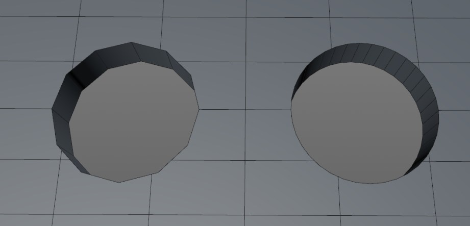
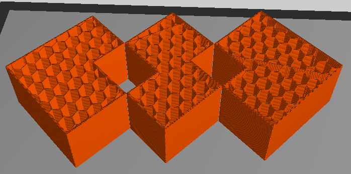
A good example of over-subdividing is making small holes on a typical home FFF printer. If you add enough subdivisions to make a perfectly smooth hole the printer won’t be able to properly translate so many small moves. It’s better to use a lower edge count which will produce a smoother printed opening.
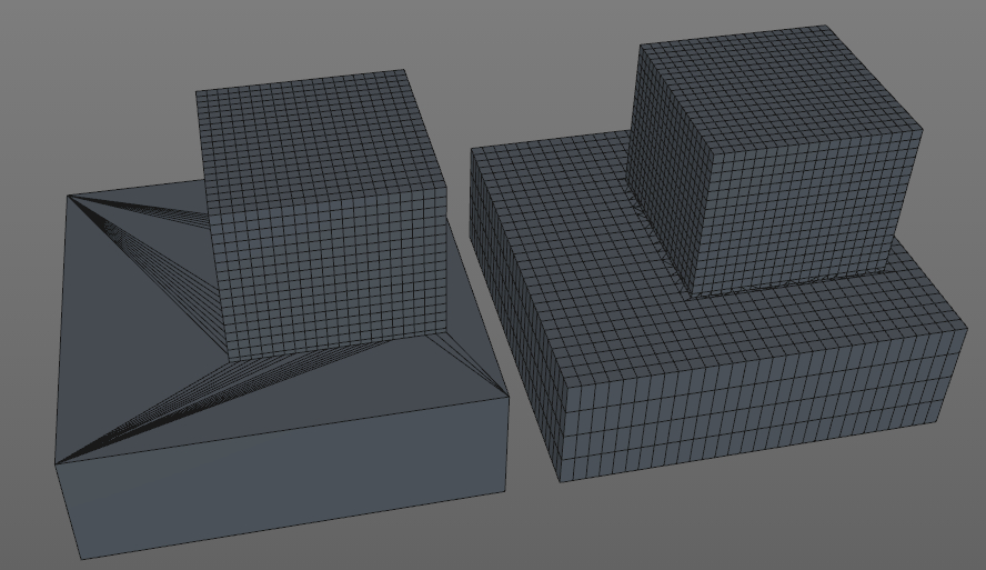
Adding subdivisions to something like a sphere is pretty straightforward; add more divisions, sphere looks smoother. But what if you want to make a cube with rounded edges? I could subdivide the heck out of it and it will still look like a cube–this is where you need a subdivision surface, AKA “subD” modeling–not to be confused with regular subdividing. SubD modeling is kind of the polygon equivalent of modeling with NURBS since it’s good for smooth organic surfaces but doesn’t take as much computing power. Adding a subD modifier to an existing model will add subdivisions AND a smoothing algorithm, similar to the render smoothing, but in this case the actual geometry is smoothed.
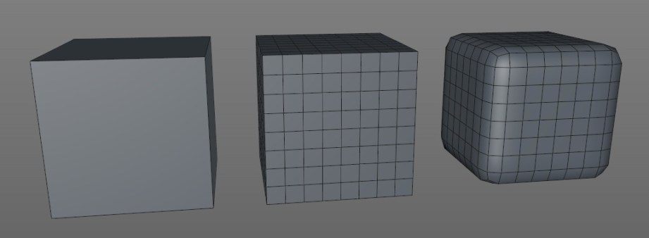
Like NURBS, subD modeling uses a ‘cage’ to control the high-resolution model and the subdivisions can be adjusted at any time. The cage is basically the low-poly model that you applied the subD to. Trying to adjust a high-poly mesh would be a nightmare, so by using the low-poly cage we can easily make changes. The catch to subD modeling is it may smooth too well and you will have to add in additional ‘edge loops’ to more clearly define edges and features. This is where modeling in quads is really important since a model not in quads is very hard to properly modify as a subD surface.
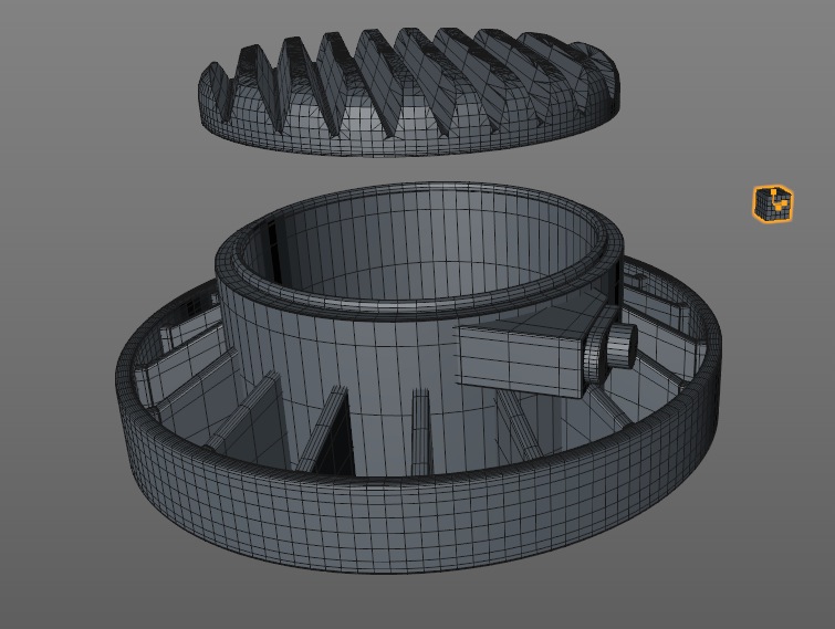
Boole-Ya!
Booling uses add, subtract and intersect functions to combine geometry in different ways. It’s an important feature for modeling and for 3D printing in particular. You can easily make a model by taking a bunch of primitives and sticking them together and it will look okay and render okay, but probably won’t print well–if at all.
The problem is mashed together parts have hidden geometry that is inside the other parts, but still gets sliced and printed. This can cause problems with the slicing software–making it take longer to finish, or even crash–and the resulting model will often be messed up, have holes or weird geometry problems.
Even if the model slices properly it will take longer to print and use more materials since all that hidden geometry is being printed as well. In the long run it’s far better to suck it up and combine all the parts into one shell using the boole function.
If boole operations are spitting out funky geometry, make sure neither object has typical geometry problems (see repair section at end of article). Good news for CAD users, you should get clean, problem-free booles almost every time.
The Shell Game
Shelling is mainly used to cut down on weight and save money when printing on machines that use a powder material such as 3DP, CJP or SLS. As you may recall, the powder printers use the loose powder in the print bed as support material. If the model is hollow, the support material from inside the model can be removed and you won’t be charged for it. In some programs you can simply use a hollow function, specify the wall thickness and blamo! it’s done. Unfortunately, most programs don’t have this function, so you have to do it manually by creating an inner shell.
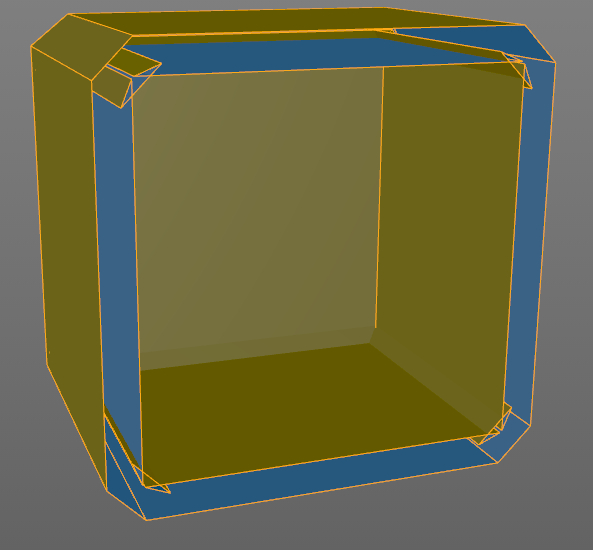
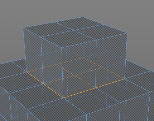
First, you want to boole together most of the larger pieces which make up your model. This will create one continuous shell and if you’re lucky you can select the whole thing and extrude the surface inward, basically making a duplicate shell inside the original, like we did in the MintyBoost video. Unfortunately, this does not work for a lot of models, so keep a close eye on the inner shell when you try this. If geometry starts to intersect itself or freak out, it’s not going to work.
The more tedious option is to boole the entire model together to make one large shell and build the inner shell manually. This can be done by putting a simple primitive, such as a cube in the center of the model and carefully extruding and adjusting it outward to create a shell. It’s helpful to use the wireframe or x-ray mode in the side and top views so you can see inside. Remember that reference cube we made? Use it to eyeball the proper wall thickness for the shell, it doesn’t have to be pretty or even super precise since it’s on the inside and will never be seen. The last step is to combine that cube with the model and then cut escape holes for the support material.
If you want to see what this gains you, upload the same model, one solid and one hollowed to Shapeways and get a quote for strong and flexible material; there are savings to be had.
This method won’t gain you anything on a home FFF printer since you can specify wall thickness (shells) and fill percentage in the slicing program. I will often have multiple versions of the same model tailored for specific printers.
Don’t Worry, She’ll Hold Together
The final step is to check your model for potential issues which may cause print problems. Some flaws are easy to identify, and some can be really difficult to pinpoint and fix. Here are some typical issues:
Not watertight – this shouldn’t happen with a CAD model, but a polygon model needs to be completely sealed–so if you were to theoretically fill the interior with water, it won’t leak. This can be an obvious problem, such as a large face that’s missing, but is much harder to find if it’s a very small face. It’s also possible for an object to look completely fine and have an edge that’s unattached. Using an ‘optimize’ or ‘mesh cleanup’ command will often fix this problem and/or a mesh repair program such as netfabb (see below).
Non-manifold – this is kind of an M.C. Escher, impossible geometry problem where more than two faces of an object share the same edge or vertex which is bad and will cause print errors. You may have to rebuild a portion of the object to correct this problem or use mesh repair software.
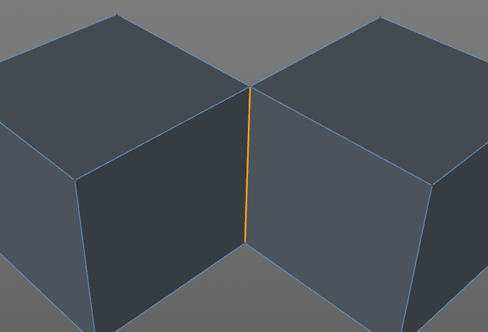
Laminate faces – this is a non-manifold problem where multiple faces overlap each other and can be really hard to spot. This often happens with the boole function when faces overlap each other and you may just have to delete a suspect area and fill it with a new polygon.
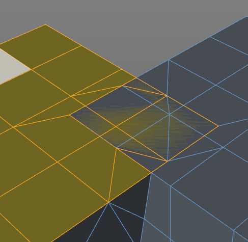
Internal faces – this often happens with extrusions if you have an ‘add caps’ function turned on. Rather than making a hollow extrusion, an interior cap is added. I do this ALL THE TIME and it can be maddening to diagnose and may cause print problems. Try using wireframe mode or go inside the object to look around and delete the face.
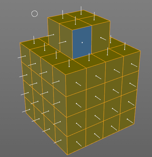
Flipped Normals – What? Each face that makes up an object has a ‘normal’ which defines what is the inside and outside and sometimes they get turned around. SketchUp is kind of notorious for doing this, but most programs will show flipped faces in a different color and/or have a little perpendicular indicator on each face. There should be an option to ‘flip’ or ‘align normals’ to solve this problem and mesh repair programs will usually fix this as well.
Other than what I quickly mentioned for each problem, some possible fixes from within the modeling program are ‘optimize’, ‘mesh cleanup’ or similar functions that will look for unused vertices, non-manifold edges and sometimes flipped normals and fix them. There may be a be a ‘tolerance’ option for combining vertices which are very close to each other. It basically tells the optimize function to combine vertices that are less than X units apart. This can be helpful for fixing watertight issues but can also combine vertices that it shouldn’t and cause new geometry problems. You may have to fiddle with the tolerance setting to get the proper results.
After doing what you can within the modeling program, it’s time to export as an STL and run it through a mesh repair program. This is a must. It doesn’t matter how carefully the model was built or how clean it looks, there are often small, hidden imperfections that will cause print errors. Some software choices are:
Netfabb is my go-to repair software that will fix most problems automatically. There is a free basic version and a cloud version which I suggest to newbies since it is completely automatic and will actually fix more problems than the desktop version. A big advantage of the cloud version is that it will take multiple parts and combine them into one mesh–the free desktop version will not. You can try having the cloud version do all of the booling for you, but be sure to check the model thoroughly for weirdness when it’s done. Rather than reinvent the wheel, I will redirect you to Shapeways, which has an excellent walkthrough of using netfabb to repair a mesh and is the exact same steps I would list.
MeshLab is free, can do a lot, and works well but hasn’t been updated in almost 2 years and can be a intimidating for newbies.
Meshmixer is another freebie from Autodesk and allows you to manipulate meshes and do some repairs but it won’t cover everything. I expect this program to add more repair features down the road.
Simplify 3D is relatively new, but has no free or even trial version so I can’t give an accurate assessment. However, it looks very promising since it combines mesh repair with a slicing engine that gives you a lot more control over how your model is printed. This is the direction I expect most software to go; integrating repair and manipulation with the slicing engine.
We continue to slog our way toward a successful print! Start with simple stuff, take your time and don’t be afraid to screw up, I do all the time! That’s part of the beauty of having a home 3D printer with relatively cheap materials, you have the luxury of many prototypes. Let us know how it goes for you in the comments and stay tuned for more tips and tricks.
Photos courtesy Sean Charlesworth unless indicated.


3 thoughts on “Bits to Atoms: 3D Modeling Best Practices for 3D Printing”
Leave a Reply
One Day Builds
Adam Savage’s One Day Builds: Life-Size Velocirapt…
Adam embarks on one of his most ambitious builds yet: fulfil…

Show And Tell
Adam Savage’s King George Costume!
Adam recently completed a build of the royal St. Edwards cro…

All Eyes On Perserverance – This is Only a Test 58…
We get excited for the Perserverance rover Mars landing happening later today in this week's episode. Jeremy finally watches In and Of Itself, we get hyped for The Last of Us casting, and try to deciper the new Chevy Bolt announcements. Plus, Kishore gets a Pelaton and we wrack our brains around reverse engineering the source code to GTA …
Making
Adam Savage in Real Time: God of War Leviathan Axe…
Viewers often ask to see Adam working in real-time, so this …
One Day Builds
Mandalorian Blaster Prop Replica Kit Assembly!
Adam and Norm assemble a beautifully machined replica prop k…
House of MCU – This is Only a Test 586 – 2/11/21
The gang gets together to recap their favorite bits from this past weekend's Superb Owl, including the new camera tech used for the broadcast and the best chicken wing recipes. Kishore shares tips for streamlining your streaming services, and Will guests this week to dive into the mind-bending implications of the latest WandaVision episod…

One Day Builds
Adam Savage’s One Day Builds: Royal Crown of Engla…
One of the ways Adam has been getting through lockdown has b…
Making
Adam Savage Tests the AIR Active Filtration Helmet…
Adam unboxes and performs a quick test of this novel new hel…
Making
Weta Workshop’s 3D-Printed Giant Eyeballs!
When Adam visited Weta Workshop early last year, he stopped …
One Day Builds
Adam Savage’s One Day Builds: Wire Storage Solutio…
Adam tackles a shop shelf build that he's been putting off f…
This is kind of a weird article, reads like it’s trying to be technical and nontechnical at the same time. Who knew that I’d be getting a primer on mesh topology while reading Tested?
But anyway, the article missed one piece of software that’s very useful for anyone trying to do serious mesh modeling, which is Blender. Aside from being great modeling software, it’s got a 3d print toolbox where you can check meshes for non-manifold edges, duplicate edges, sharp edges, thin walled geometry, geometry that is at too steep an angle… a whole manner of things. And it’s integrated right into the software, so you can analyze the mesh, and then click to find out where the issue is. That way you dont have to spend time searching the model visually for problems.
Stop complaining, the article is good and spread the wings of what 3D printing is. Thanks and interesting read!
Well I Liked it! Good Job Sean! This was a fun read and I think it is totally a valid subject, especially for beginners, whom this is obviously geared toward. Keep up the good work Fine Sir!