


The Volpin Project, Part 5: Bondo Strikes Back
Harrison tries to teach himself something new or refine a process with every new prop project, and that involves a bit of experimentation even during the course of one build. This week, we learn about the some of the trial and error used to craft the different casing segments of the Halo 4 Needler prop.
There’s a bit of experimentation that goes into each project I do. This has to be metered somewhat, as most of my work is also done for clients who have deadlines and requirements for their commissions. Still, I try to teach myself something new or refine my process from project to project, or even during the course of a singular build. In the last entry, I detailed the process of using ribs and spines cut from MDF to make a complex shape. There were some issues with this process.
Most notably, sanding past the MDF or into the foam produced frustrating variations in the surface. Bondo is much denser than MDF, which in turn is far denser than the foam I was using. Getting a consistent even surface became a struggle, as sanding across all three types of materials with the same amount of pressure would produce divots in the part I was shaping. For the foregrip and lower casing of the Needler, I tried a variation on the technique.
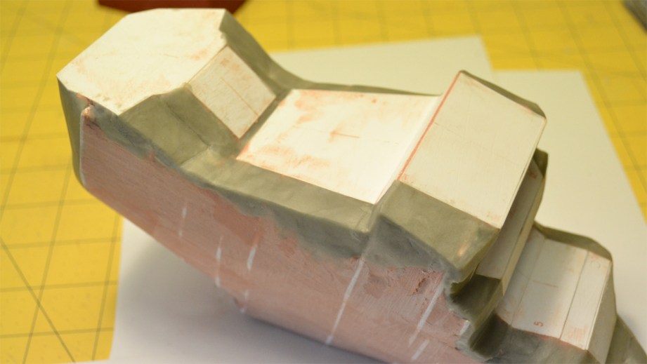
The underlying structure of the base build is very similar to the top, but the ribs are now made from .060″ styrene. There are a lot more ribs on these parts as their curvature is much more intricate than the top casing, so I used styrene trimmed on my laser cutter to expedite the process a bit. I also trimmed the center spine for the foregrip out of ¼” acrylic, but that’s mostly just because it was what I had on hand and I didn’t want to run to the store just to buy one sheet of ¼” MDF for this small part.
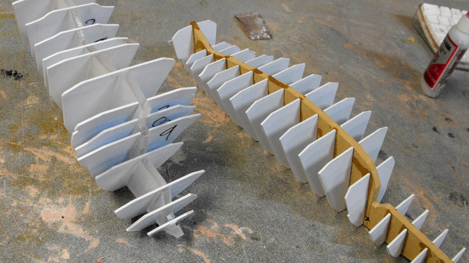
When these pieces were filled with foam, I intentionally trimmed the filler blocks smaller than the surrounding ribs. My theory here was that filling in these small recesses would result in a surface that was mostly bondo, and then shaping it would be easier and more consistent since I wouldn’t be sanding down into the foam randomly.
The beginning stages of this were ugly, at best.
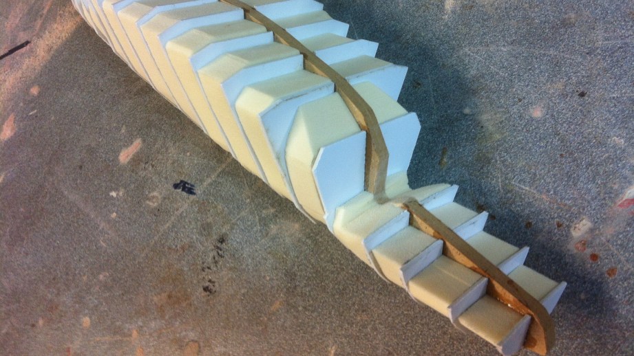
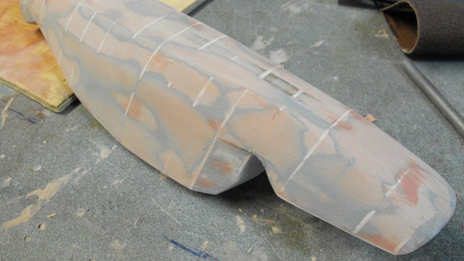
This process is more additive than the one described last time, and as such I needed to apply filler in stages. The idea is to fill up to the ribs without burying them, then smooth out the curvature later with thinner skim coats of bondo. All in all, a slower process but likely more precise than the subtractive method outlined previously. Both have their downsides though, which I’ll note in a minute.
As with before, flat panels were added with styrene and Apoxie Sculpt was used to bevel the more complex edges. The foregrip was especially frustrating in this stage.
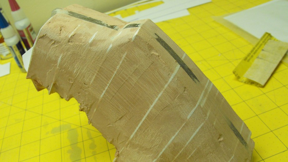
A downside to this process began to reveal itself once these parts were primed. Styrene is far denser than bondo, and I had created a very similar problem to the previous technique, but now with new materials. Sanding the sides of the part would cause the ribs to stick out just slightly–maybe 1/32″ or so–but enough for them to ruin the gradual sloping curve I was after.
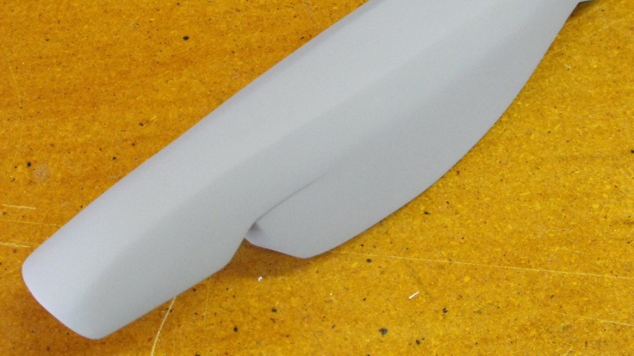
The solution here was to dremel out all the ribs, then use the surrounding areas as markers to rebuild these cavities and blend everything back into shape again! Not an ideal solution, I’ll admit. When attempting this in the future, I’ll probably look to using materials that are either the same substrate (MDF filler in MDF ribs) or very similar in density (foamed PVC or “sintra” would probably be a good match to Bondo).
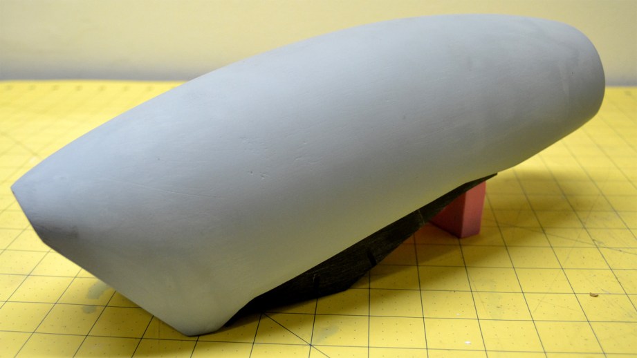
Still, at the end of the process these parts are looking good and have all the necessary symmetry I’m after for my replicas. The process itself still needs refinement, but not much more before I think I’ll be able to get good consistent results in a shorter timeframe. And you guys get to learn what not to do without all the bondo fumes and piles of used sandpaper. Win-win!
These parts are all nearly complete as far as the base shapes are concerned. It’s tempting to go in and start adding details –panel lines, indentations, markings and such–while doing all this shaping because that makes the parts look like more than lumps of gray stuff. This should be saved until after the main overall shapes are finished and symmetrical. Adding proper details relies heavily on reference points across a prop, which rely on proper symmetry of a part both in dimension and curvature. If the initial shape isn’t perfect than all the detail in the world won’t hide it.
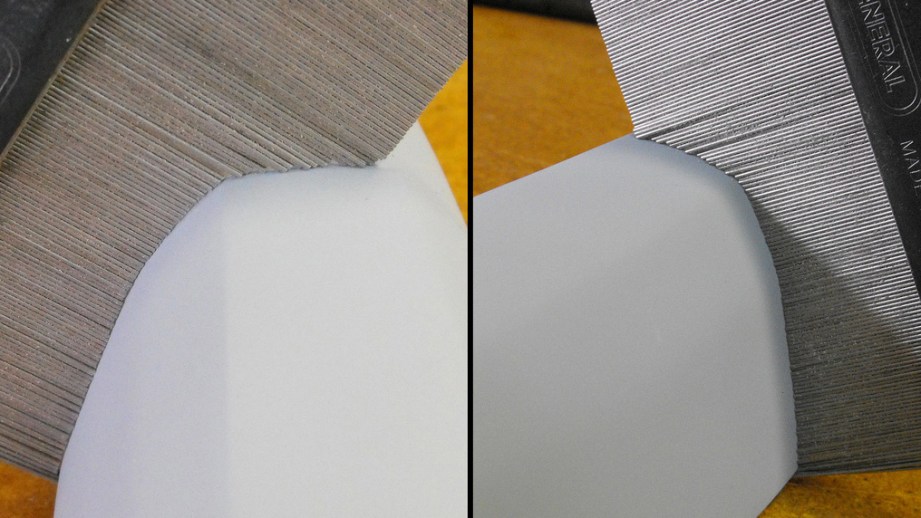
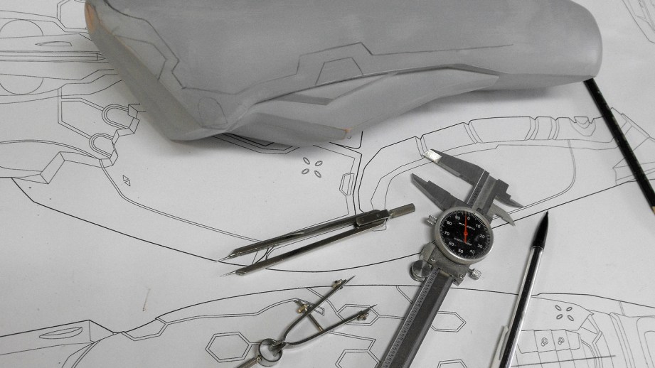
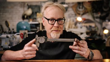
Below is a shot of the lower casing measured with a contour gauge–checking for symmetry across the left and right halves. We’re good here!
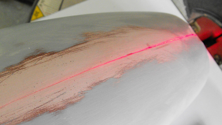
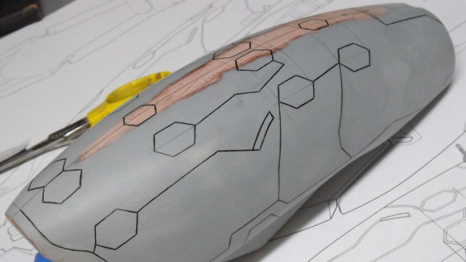
The upper casing is done at this point too, so we can start transferring the pattern for the hexagonal needle recesses as well as the panel lines onto this section. In order to make sure the details are transferred symmetrically as well as proportionally, you need a reference point. For a part like this, a centerline will work very well–one of the perspectives is drawn top-down and a lot of our measurements can be pulled from this illustration without the curvature of the part distorting the dimensions too much. I don’t have a laser level, so I used the laser guide on my chop saw to mark out the center line (it also helped to sand a little bit down to the center MDF spine.)
Generally for this kind of thing I use a couple measuring tools. A dial caliper is a good start, and having a set of drafting compasses (with metal points on both ends) will help a lot. Beyond that, grab a roll of masking tape and a pencil and you’re set.
I’ve done a lot of the line work on this part already, but the principle is the same whether you’re making the first mark or copying two halves symmetrically. In the below example one line is being transferred to the other side of the top casing, but if you’re just starting out you’d take your measurements from the blueprints instead. When you’re just starting out, the best place to take measurements from is the center line made earlier. As you get more and more patterns onto the part, you can start getting references points from the lines you’ve already transferred.
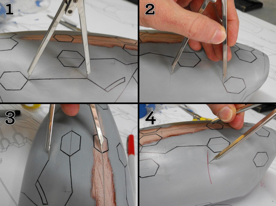
- Measure the line you want to transfer with a compass. Hold this measurement, and carry it over to the opposite side of your part.
- Put one end of the compass on the reference point (in this case the hexagon point) and scribe a curved line with the other end.
- Pick a new reference point (the point on the center hexagon in this image) and measure to the end of the line you’re copying
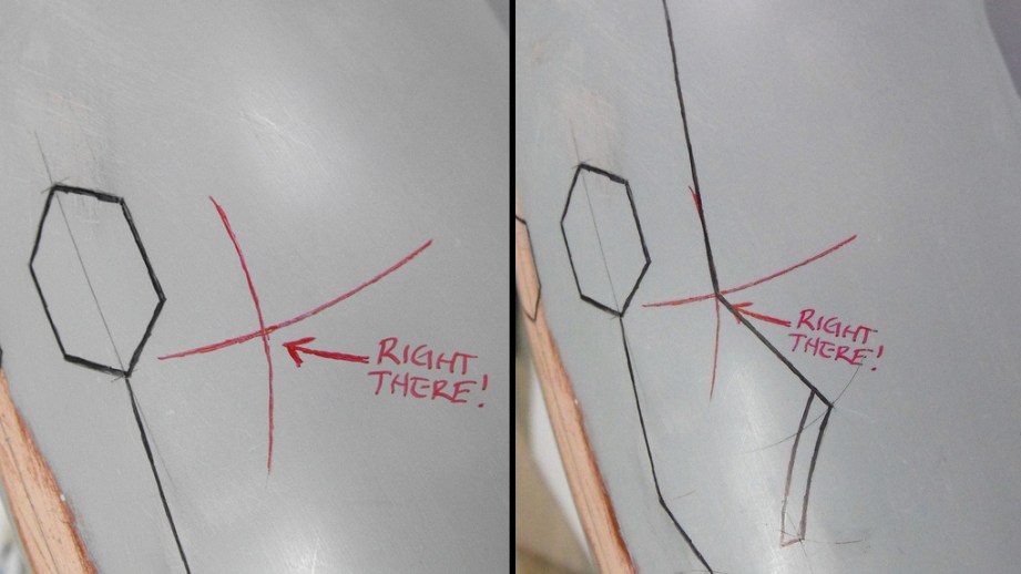
- Scribe another curved line. The end point of your line is where the two scribed curves intersect.
I’ve accentuated the intersection here in red to give a better idea of what I’m talking about, but essentially all of the lines on the top casing of the needler were transferred in this way.
Repeat for… well, everything! There are a TON of panel lines on the Needler, so this process is going to take me a while.
That’s it for today; in the next segment I’m hoping to have most of the paneling scribed and be working on final polish of the parts before moldmaking. There’s still a lot of sculpting to go for a few components (and still two pieces I haven’t even started yet!) but the project is shaping up pretty quickly.
The Volpin Project, Part 1: Introductions
The Volpin Project, Part 2: References and Blueprinting
The Volpin Project, Part 3: Selecting Materials
The Volpin Project, Part 4: Taking Shapes


7 thoughts on “The Volpin Project, Part 5: Bondo Strikes Back”
Leave a Reply
One Day Builds
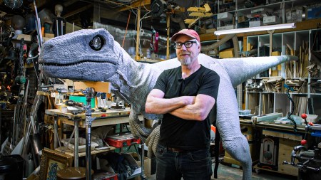
Adam Savage’s One Day Builds: Life-Size Velocirapt…
Adam embarks on one of his most ambitious builds yet: fulfil…

Show And Tell
Adam Savage’s King George Costume!
Adam recently completed a build of the royal St. Edwards cro…

All Eyes On Perserverance – This is Only a Test 58…
We get excited for the Perserverance rover Mars landing happening later today in this week's episode. Jeremy finally watches In and Of Itself, we get hyped for The Last of Us casting, and try to deciper the new Chevy Bolt announcements. Plus, Kishore gets a Pelaton and we wrack our brains around reverse engineering the source code to GTA …
One Day Builds
Mandalorian Blaster Prop Replica Kit Assembly!
Adam and Norm assemble a beautifully machined replica prop k…
House of MCU – This is Only a Test 586 – 2/11/21
The gang gets together to recap their favorite bits from this past weekend's Superb Owl, including the new camera tech used for the broadcast and the best chicken wing recipes. Kishore shares tips for streamlining your streaming services, and Will guests this week to dive into the mind-bending implications of the latest WandaVision episod…

One Day Builds
Adam Savage’s One Day Builds: Royal Crown of Engla…
One of the ways Adam has been getting through lockdown has b…
Making
Adam Savage Tests the AIR Active Filtration Helmet…
Adam unboxes and performs a quick test of this novel new hel…
Making
Weta Workshop’s 3D-Printed Giant Eyeballs!
When Adam visited Weta Workshop early last year, he stopped …
One Day Builds
Adam Savage’s One Day Builds: Wire Storage Solutio…
Adam tackles a shop shelf build that he's been putting off f…
Show And Tell
Mechanical Dragonfly Automata Kit Build and Review
Time for a model kit build! This steampunk-inspired mechanic…
Thanks for these, super interesting reads.
Looking forward to the lines, thats when things get real 🙂
This is really becoming my favourite feature on Tested. Having built some props in the past, this is really inspiring stuff.
That’s some impressive work right there. I’m loving this series man.
Some of the most interesting articles on Tested. I was actually trying to wait until they were all up on the site, but I caved last night and read them all. Amazing work, you’re a ridiculously talented guy!
From what I can tell, your plans are an orthographic projection. How to you accomodate for the error created when transferring the dimension from the plan or elevation view to the 3D piece?
My usual method involves trying to hold a bunch of rulers perpendicular to one another and the piece.
Measuring is the bane of my existence