


Bits to Atoms: Building the Millenbaugh Motivator, Part 3
Progress on the Millenbaugh Motivator marches on! All the measurements have been made and a rough version has been modeled and approved by Adam. This week we take a look at modeling the final version and speccing hardware.
Progress on the Millenbaugh Motivator marches on! All the measurements have been made and a rough version has been modeled and approved by Adam. This week we take a look at modeling the final version and speccing hardware.
I decided to tackle the ‘valve arms’ first since I wasn’t sure how to build them. They look relatively simple but on closer inspection there’s multiple compound curves, plus the forked portion at the back and I couldn’t easily build them using my regular techniques. I ended up drawing them as 2D splines (curve described by interpreting points) on top of the reference photo–if you are comfortable using the pen tool in Illustrator or Photoshop, this is the same idea. I was able to give the spline thickness by extruding it and then used planes and simple shapes to cut out the rear fork and the front slope.
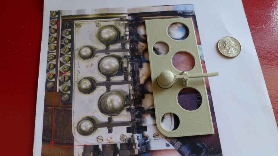
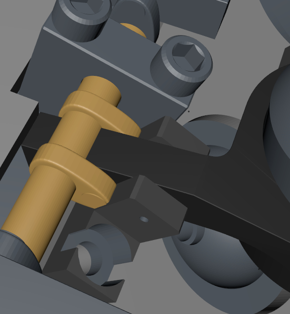
Early on, it was tough picturing the size of some of the parts. When you’re constantly looking at blown up pictures for reference and working in 3D where things are floating in space, you start to picture things much bigger than they really are. Adam mentions this in our video when he was convinced the motivator was too small until he actually placed it on the glove. I did a test print on my MakerBot and it looked way too small, so I printed a 1:1 reference picture to easily compare parts and they were right on. I was even able to print the pivot and if a part was printable on the MakerBot (even if it was a little rough) it should print on the high-end printer without any problems.
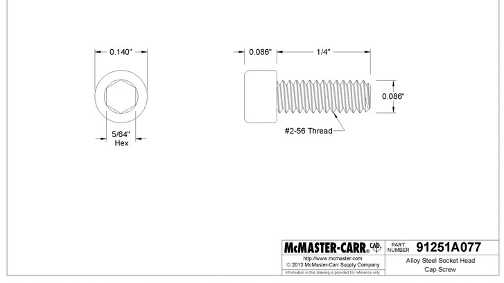
Initially, Adam told me he would spec out all the actual hardware–screws, nuts, bearings, etc., but after the first test print I realized it would be easier for me to do it. I needed to know the exact fastener sizes in order to build the parts around them. Using the Photoshop measurements I picked an approximate fastener size and confirmed it using the free CAD files that McMaster-Carr supplies. I was also able to use the CAD files to import 3D models of all the hardware into Cinema 4D which made things much easier.
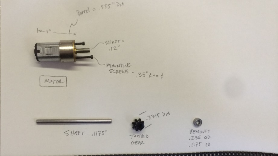
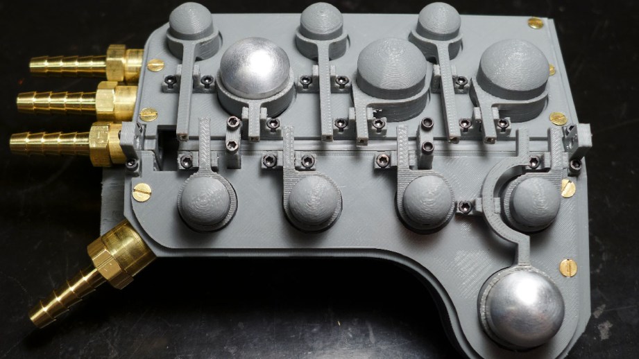
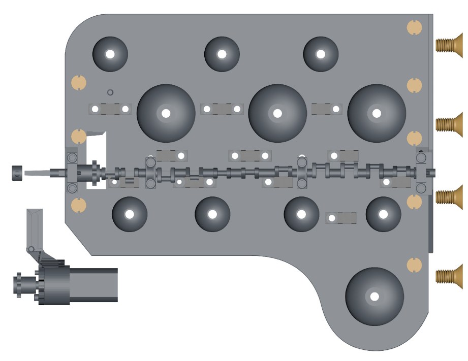
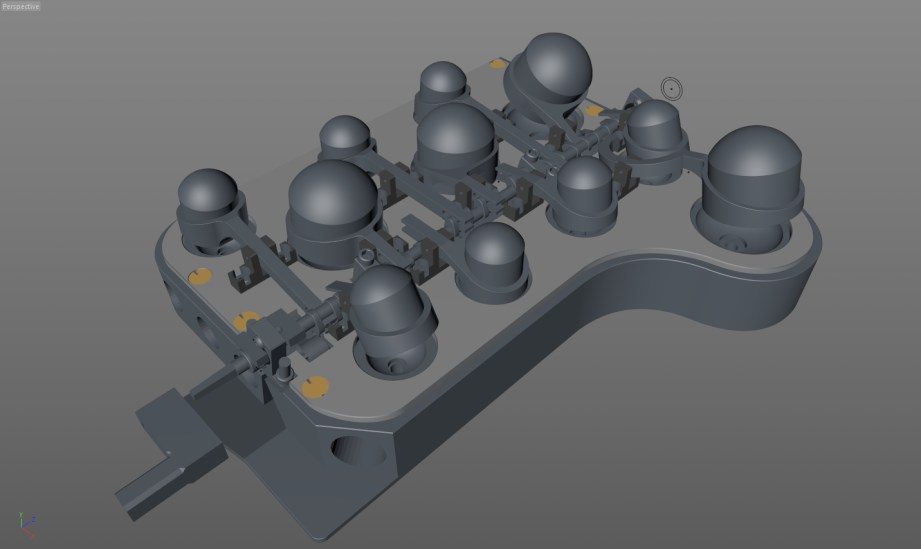
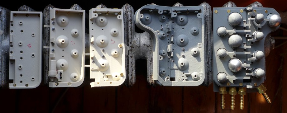
Adam was still supplying the drive mechanism for the Motivator and sent me great reference pictures of the motor, chain and bearings. I used that info to build a stand-in for the motor so I could print it out and test it with the motor mount. I used the same spline technique to build the main blocks and top plates and was able to include all the holes needed for the hardware. That gave me the basic shape for the blocks, but the valve hollows and all the details underneath needed to be cut out separately, which required many steps. If I needed to modify something I would often have to go back to the base version, tweak it and then do all the steps to cut everything out again.
Adam reminded me to not forget the LED lights and I was like, ‘what lights?’ since I had not seen any on the reference pictures. Adam said there was an LED underneath each valve so I had to shuffle things around a bit to accommodate those. Later, when Adam sent me a video he shot of the motivator running, there was indeed an LED under one of the valves, but the rest were dark. I heard him comment to the operator that the LED looked cool. The operator said it was just the operating light from the speed control and I think Adam liked the look and made a nice modification.
Demo video at Spectral Motion showing the firing order and the elusive LED. CREDIT: Adam Savage
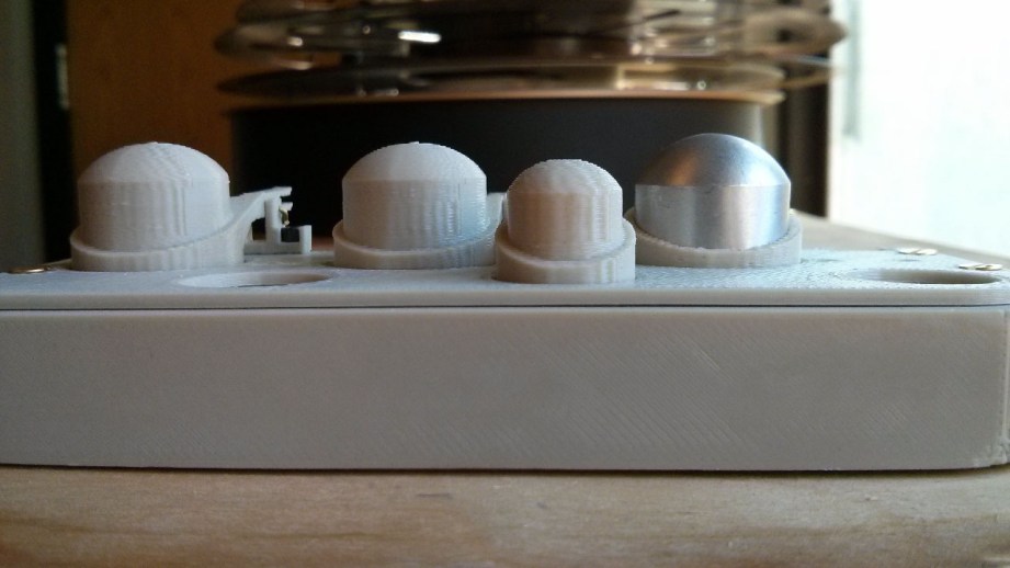
Adam had an epiphany–he realized that the valve dome looked just like the end of a cigar tube.
Things were progressing well–I was up to version 3 of the main block–and Adam had an epiphany. He realized that the valve dome looked just like the end of a cigar tube so why not use those instead! I was game, so my wife and I spent a Saturday afternoon going to eight different NYC cigar shops in search of the perfect cigar tube. Explaining that I needed their crappiest cigar that came in a metal tube about ‘this big’– and then pulling out a pair of calipers was fun.
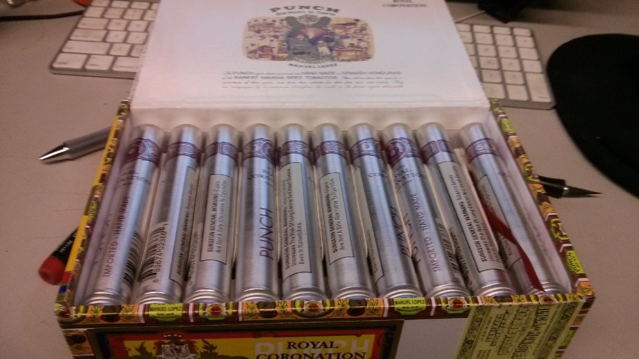
We finally found a suitable tube for the large dome but they ran $12 each and since we were building three motivators that was $150 worth of cigar tubes, not counting the small domes! Thanks to the research skills of Mrs. Charlesworth, we learned a lot about cigar sizes, types of cigars and cigar cases (thanks Reddit!) and ultimately discovered that cigar tubes don’t come in the size needed for the small domes. Adam still wanted to forge ahead, he figured the large tubes would save him some work and he would lathe the small ones. I was able to track down a 30 count box of the right cigars for much cheaper online and Adam sent them my way. And since neither Adam nor I smoke and he just wanted the tubes, my father-in-law became the very happy owner of a bunch of tubeless cigars.
Eventually, Adam sent me the actual motor, drive chain and bearings so I could do a test assembly before the final prints. The real motor differed slightly from my stand-in, so further modifications were needed–it was a really tight fit, but I was able to squeeze it in along with an adjustable motor mount. Everything was lining up and I finally had to build what I had been dreading–the crankshaft.
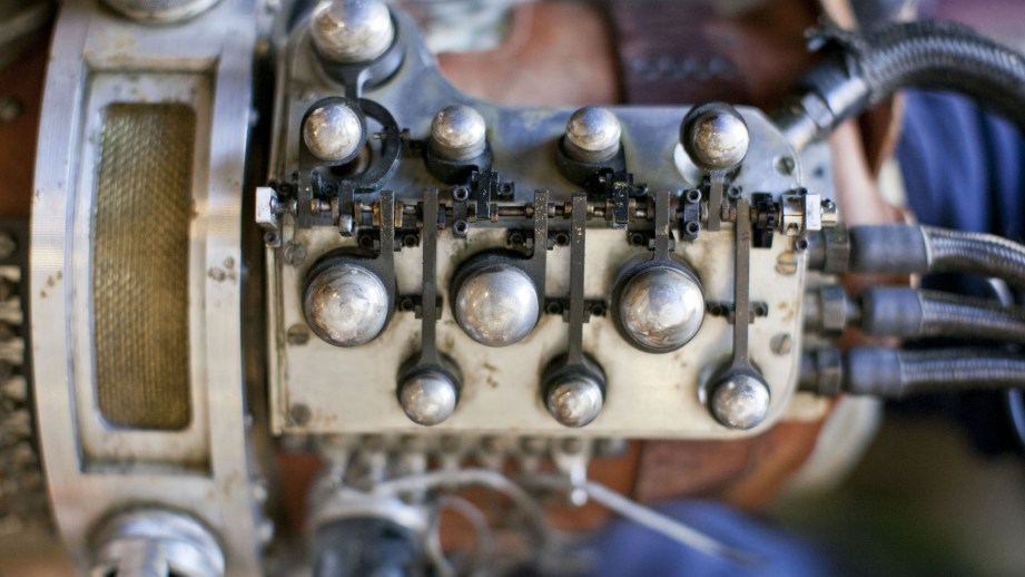
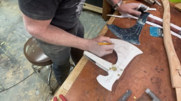
To design the crankshaft, I needed to figure out the firing order of the valves and used the same video that the LEDs showed up in. Going frame-by-frame, I figured out the correct order and started laying out the crankshaft. I posed each valve in it’s firing order, created an offset (crank pin) for one valve and copied it for all the others, adjusting the rotation as needed. The clearances were so tight that I often had problems with the back of the arms hitting the block or the crank pin popping out of the arm. You could see from the reference photos that they had similar problems on the original. The curved arm is a great example as you can see they soldered a cap on the end because the crank pin was popping out.
I thought I was finished and tested the crankshaft by rotating it within the program only to discover that it rammed right into the arm pivots on the right side block. Oh boy. There’s only so many measurements you can get from the reference pictures and I assumed that the crankshaft was centered on the seam between the two blocks – it wasn’t. I needed to move the whole thing back toward the left which set off a week of revisions. In order to move the crankshaft, I had to move the crankshaft mounts, which required changes to the blocks, which messed up the alignment of other hardware that had to be tweaked – it was a nightmare. This is a good example where CAD modeling may be the better choice since it’s meant for mechanical modeling and even simulating mechanisms.
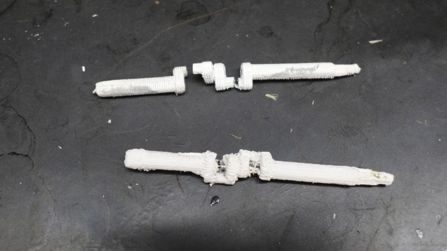
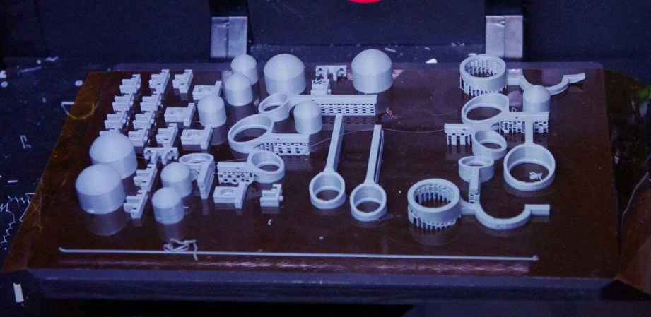
I finally got the crankshaft laid out, but it needed a final test print before dropping the big bucks on the fancy printer. Up until this point, the MakerBot had managed to print everything but the crankshaft was just too small, spindly and precise to print properly. I tried every trick in the book including printing with support material.
I also have a dual head machine so I can print ABS plastic on one extruder and HIPS support material on the other. HIPS plastic can be dissolved in limonene–a citrus based product–which won’t affect the ABS. The ABS model is encased in the HIPS support, making for a much better print. Alas, even this didn’t work, the crankshaft needed too much precision, was too delicate and didn’t turn out well.
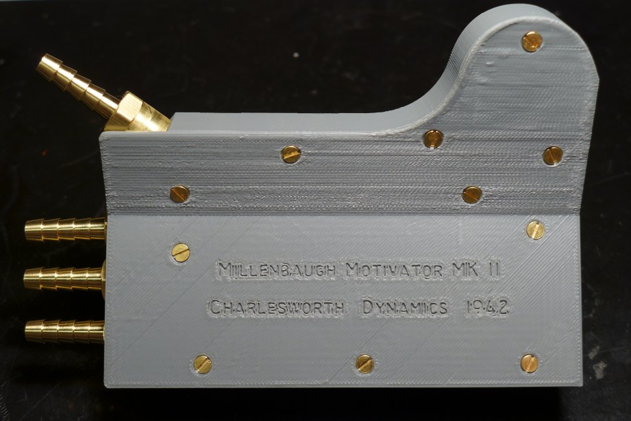
Crankshaft problems aside, I was able to print the rest of the Motivator and assemble it successfully. All the hardware worked, the motor fit and could be adjusted, and there was enough room for electronics. Adam told me to make sure to sign it in some way. In the movie, Rasputin used the Mecha-Hand to release Hellboy in 1944, so I figured that Charlesworth Dynamics finished the motivator a few years prior in 1942. Having finished a complete prototype, Charlesworth Dynamics shipped it off to Adam for approval. After a test-fit on the Mecha-Hand, Adam gave the go ahead, so we were all set for the final print!
Tune in next week for the final print, assembly and the Motivator tested under full power!
- Part 1 – Becoming The Inventern
- Part 2 – Reference & Measurements
- Part 3 – Prototypes
- Part 4 – Final Print
- Part 5 – Finishing Work
All photos courtesy Sean Charlesworth unless otherwise indicated.


7 thoughts on “Bits to Atoms: Building the Millenbaugh Motivator, Part 3”
Leave a Reply
One Day Builds
Adam Savage’s One Day Builds: Life-Size Velocirapt…
Adam embarks on one of his most ambitious builds yet: fulfil…

Show And Tell
Adam Savage’s King George Costume!
Adam recently completed a build of the royal St. Edwards cro…

All Eyes On Perserverance – This is Only a Test 58…
We get excited for the Perserverance rover Mars landing happening later today in this week's episode. Jeremy finally watches In and Of Itself, we get hyped for The Last of Us casting, and try to deciper the new Chevy Bolt announcements. Plus, Kishore gets a Pelaton and we wrack our brains around reverse engineering the source code to GTA …
One Day Builds
Mandalorian Blaster Prop Replica Kit Assembly!
Adam and Norm assemble a beautifully machined replica prop k…
House of MCU – This is Only a Test 586 – 2/11/21
The gang gets together to recap their favorite bits from this past weekend's Superb Owl, including the new camera tech used for the broadcast and the best chicken wing recipes. Kishore shares tips for streamlining your streaming services, and Will guests this week to dive into the mind-bending implications of the latest WandaVision episod…

One Day Builds
Adam Savage’s One Day Builds: Royal Crown of Engla…
One of the ways Adam has been getting through lockdown has b…
Making
Adam Savage Tests the AIR Active Filtration Helmet…
Adam unboxes and performs a quick test of this novel new hel…
Making
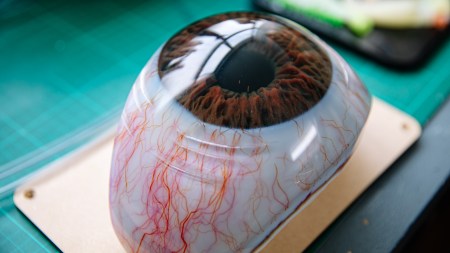
Weta Workshop’s 3D-Printed Giant Eyeballs!
When Adam visited Weta Workshop early last year, he stopped …
One Day Builds
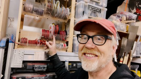
Adam Savage’s One Day Builds: Wire Storage Solutio…
Adam tackles a shop shelf build that he's been putting off f…
Show And Tell
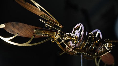
Mechanical Dragonfly Automata Kit Build and Review
Time for a model kit build! This steampunk-inspired mechanic…
Wow, that’s a lot of work. Looks great. Seems like it could be a good kit to sell back to the RPF community.
Full HBP of prints…No bow on your HBP?
As someone who just spent two days getting back into modelling in C4D, I am floored by your precision :p
I think the most amazing thing is that you were able to design it without using a CAD program, which would have made the mechanical testing way easier. But let me tell you, it would have been the same pain in the a to rework the crankshaft in CAD as it was in your program. I spent halve a day just because i was about 10mm off. ( I’m from Germany and can’t figure out how you are able to produce this work in .inch) But after all it really looks great and maybe you will eventually try out some CAD tools. (I really like the Inventor software due to the fact thats the workflow is similar to building LEGOs).
Thanks very much. I do plan on putting together some kits, just working out some tweaks. My first bed on the 2X was way warped – off by .7mm from end to end! The second one was right on. I have one of Carl’s x-ends to install and will be getting a set of your arms at some point too.
Thanks, I really like modeling in Cinema, it has a lot of nice tools
I have SolidWorks but just haven’t had the time to learn it. Having spent time with product designers who do use it a lot, there are things that I have built that they said would be really hard to do in CAD. This is the reason you often end up bouncing between 3 different programs to get the end result. Also, as an American, I totally agree with you – I model everything in metric!
I have a SolidWorks window open right now! I find it a very simple program, but I learned and spent almost a decade using ProE, which is like SolidWorks on steroids.
But, yeah, anything that is easily expressible as math is a snap. The animation of the arm looks like something you could model up in three or four features. Once you get into compound curves and the like, it starts getting really complicated.
I totally agree with the opinion that it had been way more difficult to build the octopod with CAD, due to the fact that it is totally shitty when it comes to freeforming or freestyle modelling. Although it may have been the easier tool to build the millenbaugh motivator in, due to its mechanical buildup with pretty “simple” geometrical shapes. That’s the reason why I am so amazed of your work in Cinema 4D.
By the way, thanks for the great articles, they really helped me pitching the idea of a 3D printer to my boss 🙂 and when I showed him what could be done with rubbery materials he was absolutely stunned.
I’m really interested in SpaceClaim software. I spoke with them at a 3D printing expo and they say their software combines elements of CAD and mesh modeling which would be perfect. Their demos look pretty convincing.