


Bits to Atoms: Modding ‘The Getaway’ Pinball Machine
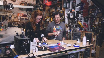
Time to take a field trip to the local pinball arcade! Jeremy and Sean take Bits to Atoms on location to modify The Getaway: High Speed II pinball machine to work with a real stop light. And to do that, they have to dive inside the machine to see how it works.


25 thoughts on “Bits to Atoms: Modding ‘The Getaway’ Pinball Machine”
Leave a Reply

One Day Builds
Adam Savage’s One Day Builds: Life-Size Velocirapt…
Adam embarks on one of his most ambitious builds yet: fulfil…

Show And Tell
Adam Savage’s King George Costume!
Adam recently completed a build of the royal St. Edwards cro…

All Eyes On Perserverance – This is Only a Test 58…
We get excited for the Perserverance rover Mars landing happening later today in this week's episode. Jeremy finally watches In and Of Itself, we get hyped for The Last of Us casting, and try to deciper the new Chevy Bolt announcements. Plus, Kishore gets a Pelaton and we wrack our brains around reverse engineering the source code to GTA …
Making
Adam Savage in Real Time: God of War Leviathan Axe…
Viewers often ask to see Adam working in real-time, so this …

One Day Builds
Mandalorian Blaster Prop Replica Kit Assembly!
Adam and Norm assemble a beautifully machined replica prop k…
House of MCU – This is Only a Test 586 – 2/11/21
The gang gets together to recap their favorite bits from this past weekend's Superb Owl, including the new camera tech used for the broadcast and the best chicken wing recipes. Kishore shares tips for streamlining your streaming services, and Will guests this week to dive into the mind-bending implications of the latest WandaVision episod…

One Day Builds
Adam Savage’s One Day Builds: Royal Crown of Engla…
One of the ways Adam has been getting through lockdown has b…

Making
Adam Savage Tests the AIR Active Filtration Helmet…
Adam unboxes and performs a quick test of this novel new hel…
Making
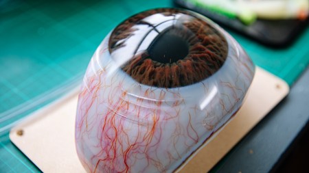
Weta Workshop’s 3D-Printed Giant Eyeballs!
When Adam visited Weta Workshop early last year, he stopped …
One Day Builds
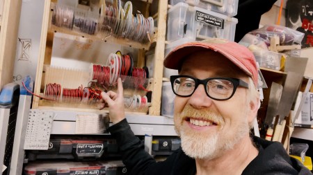
Adam Savage’s One Day Builds: Wire Storage Solutio…
Adam tackles a shop shelf build that he's been putting off f…
I was super excited to see this project! Last Halloween I created a programmable stranger things Christmas light ouija board using 11 relays and an arduino. Non led lights. It was fun watching your team work through s similar process.
I love how you guys lean into a problem and stick with it until you find a solution. It really is the creative process at work.
Bits to atoms and I’m at work?? I’m just risking getting fired, too good as always. 😉
These are really fun to watch.
It was interesting to see the fear in 110vAC, but happily grabbing low voltage live DC wiring. Not that the DC would hurt, but shorting out a component could have ruined their day.
Keep these coming!
The opto-isolators I’m most familiar with are vactrols, mostly because they’ve been used for many years in voltage controlled amplifier circuits in electric/electronic instruments. They’re used in everything from guitar pedals and amps to rack compressors to synthesizers to modulate the volume of an audio signal in a very smooth and clean fashion.
The problem-solving angle makes these videos so interesting and fun to watch.
I love all of these videos… been watching tested since the beginning (when neither of these guys were even on here). I really like all of Tested’s videos (especially the ones where something is being made), but these Bits to Atoms are my favorites.
I have been an EE for 17 years and working on this kind of stuff for 10 years before that… even though I was trying to tell you through the screen how I would have solved this problem, the best part was knowing and seeing the process that Jeremy & Shawn went through. I know it’s really hard to concentrate while being filmed but I would have liked to see some footage of the opto-isolator and arduio problem solving that happened off-camera.
By the way, Jeremy, you may have been surprised at the complication of this seemingly simple issue BUT it truly is a NON-trivial problem to solve and your solution is great! I think it actually illustrates how accessible “digital” solutions to “analog” problems can be. I have been doing this for many years and designing a capacitor, diode, resistor filter circuit is still a mind bend and time consuming because it has to be custom designed. However, with a solution like yours, it’s pretty generic and can be adjusted to fit several applications so I think it is perfectly suited to this one-off solution. WELL DONE.
Please keep these videos up. Thanks Tested.
PS. I actually have almost that exact stop light i picked up at a junk sale and have been planning for a couple of years to hook it up to an arduino. although i’m not going to hook it up to a pinball machine, you have inspired me to pull it out for my next project.
I got zapped once.
We’ll be happy to keep goofing up for your enjoyment!
Nice!
good stuff
Tagging seems to be f*#cked on this site – was hoping to tag jerware too, so please pass this message along, Sean 🙂
May I start by saying that this is one of my favourite series on Tested – Really enjoying every episode and the last pinball project (mini pinball table model) has put me on the path of a pretty insane project of which I hope to share details with you soon! And under the hood of a pinball table is my idea of proper nerd porn!
Jeremy: ecojay was correct – this is non trivial so don’t feel bad about not nailing it!
The idea of using an RC network seems good at first, but because the duty cycle of the lamp matrix waveform (approx 12.5%, given an 8×8 matrix) then it’s pretty tricksy to do anything useful with that. You enter a trade-off between being able to charge a capacitor quickly enough (needs to be small) against that capacitor holding charge for a decent amount of time (needs to be large). You can use a larger capacitor to drive a transistor (i.e., low base current, hence capacitor is discharged more slowly) which will eventually charge enough to be useful, but then it will discharge very slowly when the signal disappears, so your lamp will stay on for too long. You can do tricks like using an inverted copy of the input waveform to discharge the capacitor with a transistor or something, but it gets really messy.
The only elegant solution I can think of, i.e., low component count, is a re-triggerable monostable circuit using, for example, a 555 timer IC. A standard monostable circuit takes an input pulse and then latches its output on for a fixed duration, set with a resistor / capacitor combination. The problem is that you can’t retrigger it until the output has turned off, because of the nature of the operation of the internal flip-flop circuit (yes, that’s a real term lol).
A retriggerable monostable will maintain its output all the time it’s receiving input pulses.
It’s been a long time since I 555’d, otherwise I would have provided a useful circuit diagram for you. If that’s a path you’d be interested in, I’d be happy to dust off the cobwebs and throw something together.
(had to split my post because of an error?)
There are also dedicated retriggerable monostable chips these days though, e.g., SN54LS123 or CD74HC4538 but I have no experience with them to pass judgement on their utility.
That said, there is always a trade-off with these things. Do you spend 5 hours trying to remember this stuff, or learning it from scratch to make a circuit that uses $3 of components (plus a breadboard or proto-board or custom PCB), or do you spend 1 hour and use a $20 gadget that you’re familiar with? For a one-off, I see nothing wrong with throwing an Arduino at it if you’re uncomfortable with the alternatives if it gets the job done. Your time isn’t free, especially when you’re put on the spot. I think you earned the right to be pleased with your solution.
Oh and Sean… I love your LeChuck’s Grog shirt. I shall have to find one for myself!
That was freaking awesome. I especially love that you do cover the trial and error and problem solving. It’s hugely important for newbies to see that a successful outcome doesn’t just come into being.
I would just like to thank you both for your enthusiasm! It has gotten me interested in the electronics of Pinball machines. I started with the Pinball Makers website which seems a good deep dive into the more modern side of layout of pinball machines.
http://pinballmakers.com/wiki/index.php/Main_Page
Are there any other sites that you would recommend as resources? I’m UK based.
I’m more paranoid than you guys, and would be afraid to take a soldering iron to a working machine – I would have found or gotten Shawn to 3d-print matching connectors to tap in to where the stoplight already connects to the main wiring harness. Then if it didn’t work or the big stoplight broke or whatever, it’d be simple to remove the custom T from the circuit and it’d all still be factory fresh.
Loved it.
The location, the arcane nature of the machines themselves, the exploring and then solving the problems, the mixture of old and new tech; a marvelous piece of content all around.
Great video. More please. 🙂
Awesome as always. Can’t wait for the next project!
Great video guys, I’m new to the pinball world and currently have a Data East Jurassic Park, I would love to see a recurring series on pinball repair and modding!!!
One of my first circuits I built in electronics was traffic light controllers. This made me smile.
i’m a complete noob when it comes to electronics – most likely more so than sean. but when i saw them explain the problem on video, it sounded like it was, indeed, not as trivial as it seemed at first glance. i got there by thinking of it in terms of programming – what kind of data structure do i have (an on-off pulsing that results in a lighting effect that’s not technically ‘correct’, but is good enough for the human eye) and what kind of data structure do i want to get out of it, after processing. (for lack of a better term, a ‘correct’ signal, because the hack for small lights and human vision won’t work via relays and huge lamps)
whenever the solution is ‘add things, depending on the circumstances’, it’s going to involve some thinking so as to not trigger false positives, etc. – and this is me thinking in code terms, not in how to implement this in hardware.
glad to see my intuition was pretty much on target. 🙂
Bits to atoms has got to be hands down the best content on tested. These are so great to watch.
The optoisolators gave me an idea for an alternative solution: Add photoresistors right next to the actual stop lights in the pinball machine and hook them up to a 12V line. When the light is on, the current flows, triggering the relay. I’m just not sure if the flickering would cause a problem, but according to the Wikipedia article (https://en.wikipedia.org/wiki/Photoresistor), a photoresistor might be exactly what’s needed to smooth out the signal:
I’m not an electronics professional by any means, but I think it might work. , what do you think?
On another note, I do hope they would fix the in the comments. :/
This was a great project! I actually love the fact that it didn’t work the first time, it was neat to see the troubleshooting and final fix come together. Great work guys, keep it up!
Working in the pro audio world and loving models and making its awesome to see optical sensors being used to control lights in the same way you can manipulate audio using optical compressors. Smooth and efficient compression for pretty sounds and almost musical in the way they move the lights, truly an awesome project.