


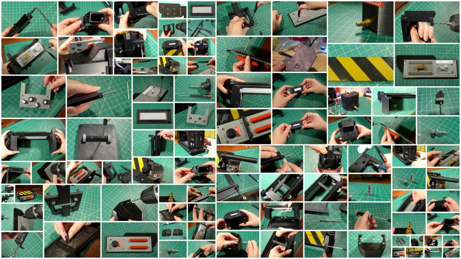
With the print pieces prepped with some painting, we begin assembling and weathering the inside of this beautiful model! (Follow along the rest of the week by joining the Tested Premium member community!)
Bits to Atoms: Designing the 3D-Printed Ghost Trap
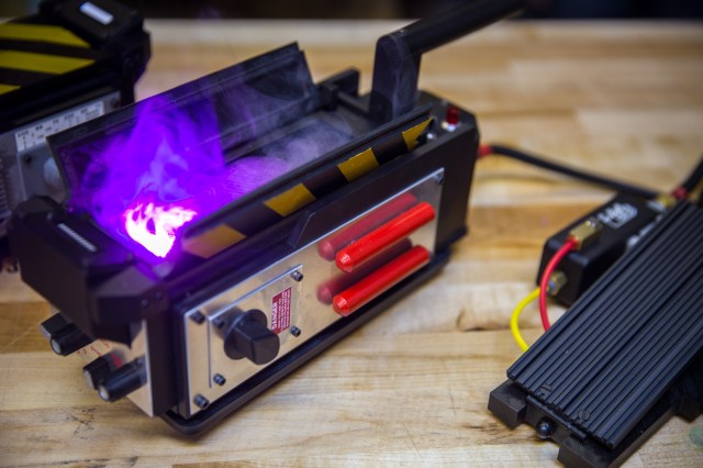
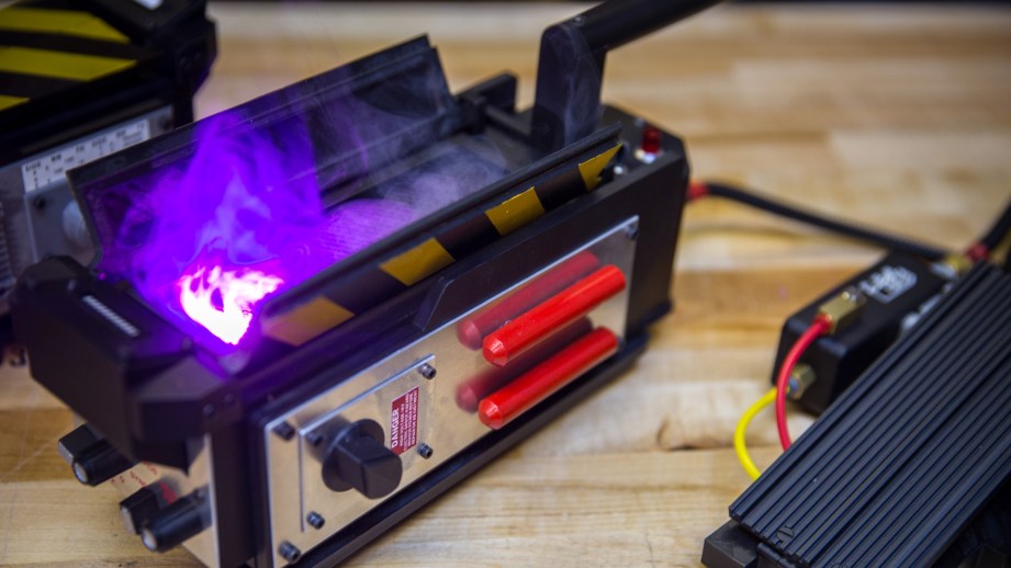
We got the tools, we got the talent – and now we have a working 3D printed Ghostbusters Ghost Trap! No – it doesn’t really capture ghosts, but it still looks really cool. Thanks to Dremel for sponsoring this project–the Dremel 3D Idea Builder printer and tools they supplied helped to make the Ghost Trap a reality.
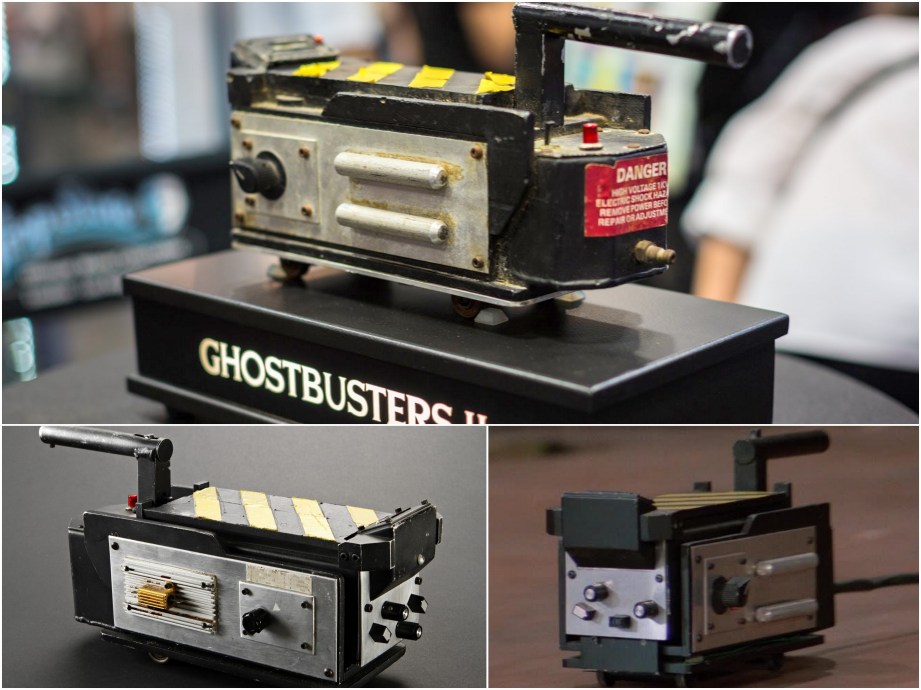
Norm and I wanted to tackle a big project and finally decided on the classic Ghostbusters Ghost Trap used in the first two movies. The trap is introduced in the classic ballroom scene where the Ghostbusters capture Bill Murray’s nemesis, Slimer. It’s rolled out underneath the unsuspecting ghost and triggered via a remote pedal. The trap opens, bright light streams out, electricity zaps Slimer is sucked inside and the doors slam shut as a bargraph illuminates, indicating the trap is full.
There are plenty of fans building Ghost Traps in many different ways – wood, plastic, foam and metal but since my specialty is 3D modeling my medium would be 3D printed plastic. There were a few things I knew right away – I wanted to make it fully 3D printable, I wanted lots of individual pieces and I wanted it to function. The first step was to round up reference material which was found in abundance on GBfans.com. Ghostbusters fans Sean Bishop and Stefan Otto had both put out detailed sets of plans for Ghost Traps and these were my starting point. I also did many screengrabs from the Blu-Rays to use as reference. Over the years, many of the knobs, lights and electronic doodads have been identified but are often hard to find, which is partly why I wanted to fully 3D print the trap.
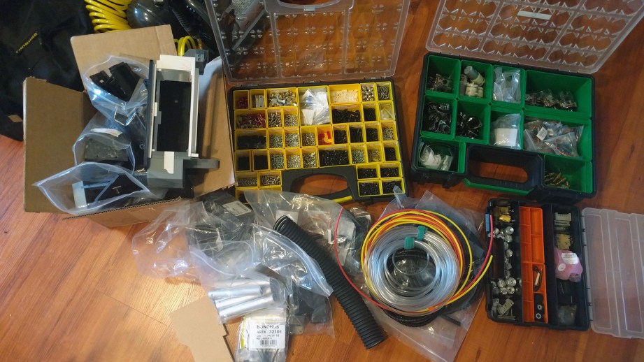
I tried to get my hands on the real parts as a reference and sometimes I was able to find manufacturer blueprints to model from. I decided to use real nuts and bolts to assemble the trap since they would look better than anything I could 3D print and would make a strong structure, good for modding. That proved to be challenging as I needed to guesstimate what size screws were used. Even with many of the parts already identified by the fan community, it still took almost a week to track everything down and select all the fasteners. Keep in mind I was also sourcing parts for the hose and pedal that activates the trap. The pedal in particular was more challenging as there were many parts that couldn’t be 3D printed such as tubing, ribbon cable, and the distinctive electronic relay on top.
There is also the question of what version of the trap to build. They vary not only by movie but what they were used for. The ‘Hero’ trap would be the nicest looking and good for close-ups. The ‘Stunt’ trap would be lightweight and good for carrying around or for, well – stunts. There might be a trap that only smokes, a trap that only lights up and pops open, a trap that rolls, etc. and they are all slightly different. I decided to base my build on the Ghostbusters 2 trap which is slightly smaller, so more likely to fit on the Idea Builder print bed and it was the one I could find plans for.
I started modeling directly from the plans but quickly ran into problems. Sometimes the plans didn’t agree, sometimes the measurements listed didn’t jibe with other parts within the same plans. I also discovered that there were some design elements on the Ghostbusters 2 trap that I simply didn’t like. Eventually I moved away from the plans and adjusted things so they looked right to my eye compared to what I was seeing on screen. I also incorporated elements from the original Ghostbusters trap such as the protruding containment cartridge which is flush on the Ghostbusters 2 trap. In the end mine ended up being a hybrid but it also made it distinctly my own.
The other goal was to make a functional trap – as in it would open and close, light up, make sound and in my dream world, smoke – all triggered via the foot pedal. This further complicated the modeling process as I needed to decide on a lot of the electronics and parts ahead of time. We’ll discuss the electronics and mechanics in a later article, but suffice it to say, I had no idea how to do any of this. I am pretty good with a soldering iron and can usually figure out the general parts needed for a project but I am no electronics expert and I needed help. Enter Tested podcast regular Jeremy Williams – creator of the Game Frame, zombie killing axes and all-around great electronics guy. Jeremy helped me figure out the components needed for a working trap so my first step was to make stand-ins.
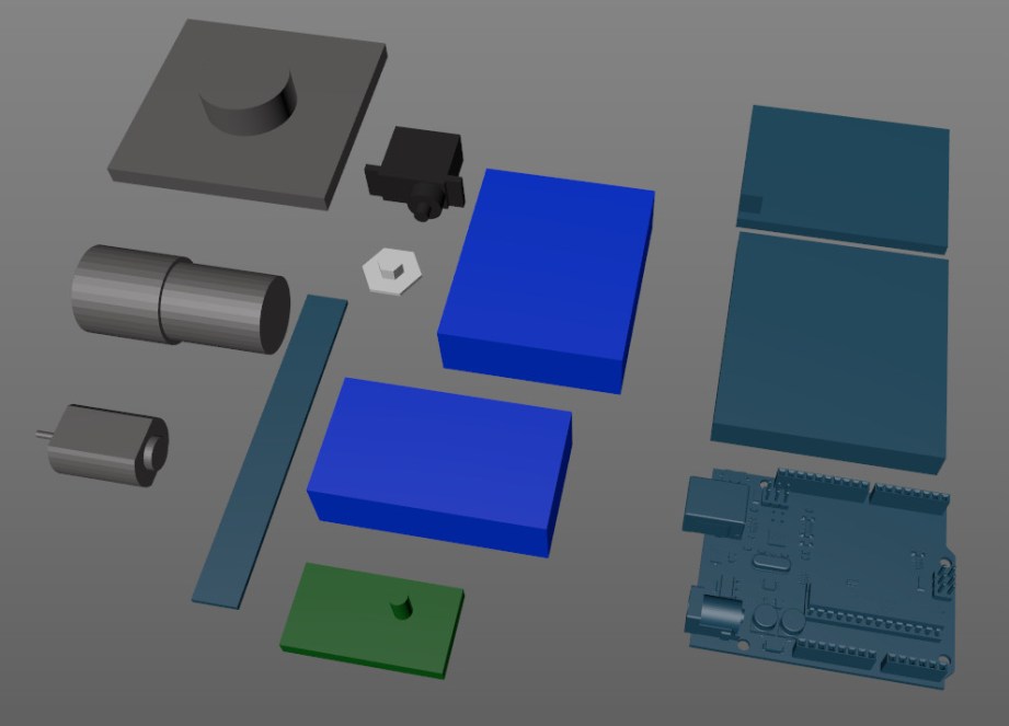
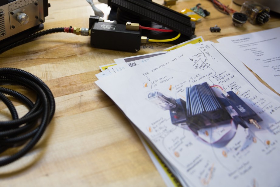
Some parts such as the Arduino have 3D models readily available and was easy to download and import as a stand-in for building around. For most of the other electronic parts I made simple shapes as stand-ins but I often needed the actual part to take measurements from, so I had to buy them before getting too deep into the modeling. At this point a lot of the design was done on paper before any more 3D modeling. Sometimes I will skip this and do my ‘sketching’ with basic 3D models, it just depends on the project.
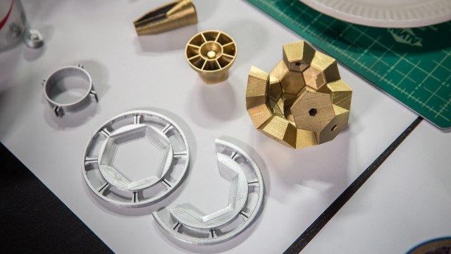
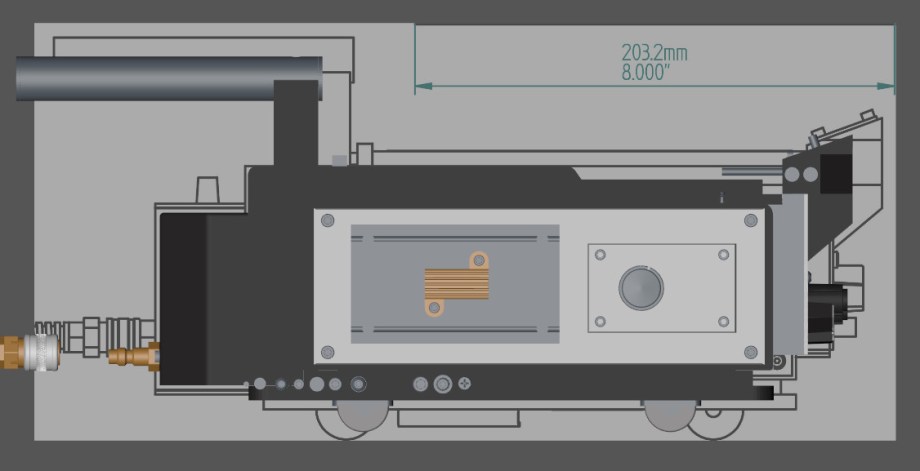
To get into the groove I started with some parts that were known quantities with exact measurements, such as the vector plate. Vector plate is a structural component for electronic cases and was one of the parts I was able to find manufacturer blueprints for. I simply traced over the blueprints using splines similar to what is used in Adobe Illustrator and then extruded the spline to make a 3D part. On the same side as the vector plate is a metal knurled knob and I had a real one to work from. No matter how much modeling I have done, I constantly run into things that stump me and in this case it was the knob’s knurled grip that I had no idea how to model. Google to the rescue – I was lucky to find an excellent tutorial online but even then it took me a few tries to get right.
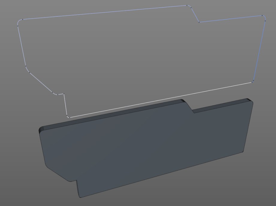
Next, I modeled the side panels which would dictate the overall size of the trap. These were also done using splines to draw the outline based on measurements given in the online plans. In the end it just didn’t look right too me compared to my reference photos, so I tweaked it a bit. When I extruded the outline to make the sides 3D I used a common material thickness of ¼” which seemed to match the actual prop and would make it easy to replicate them by other means. Since these were big parts that would take a long time to print, I felt that down the road it might be easier to cut them out of wood or plastic using a CNC router. I kept this in mind for other parts as well, such as the top doors, ‘aluminum’ plates, handle, etc. basing them all on common material sizes.
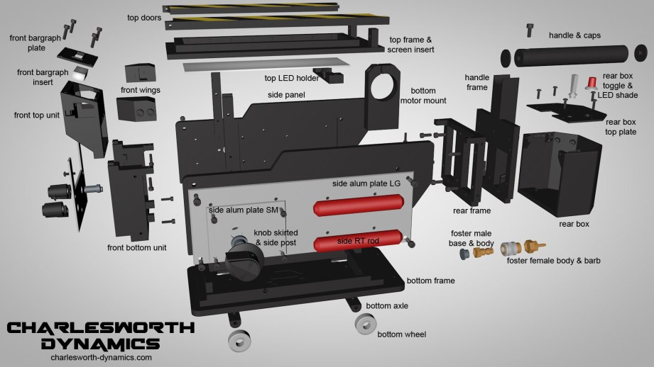
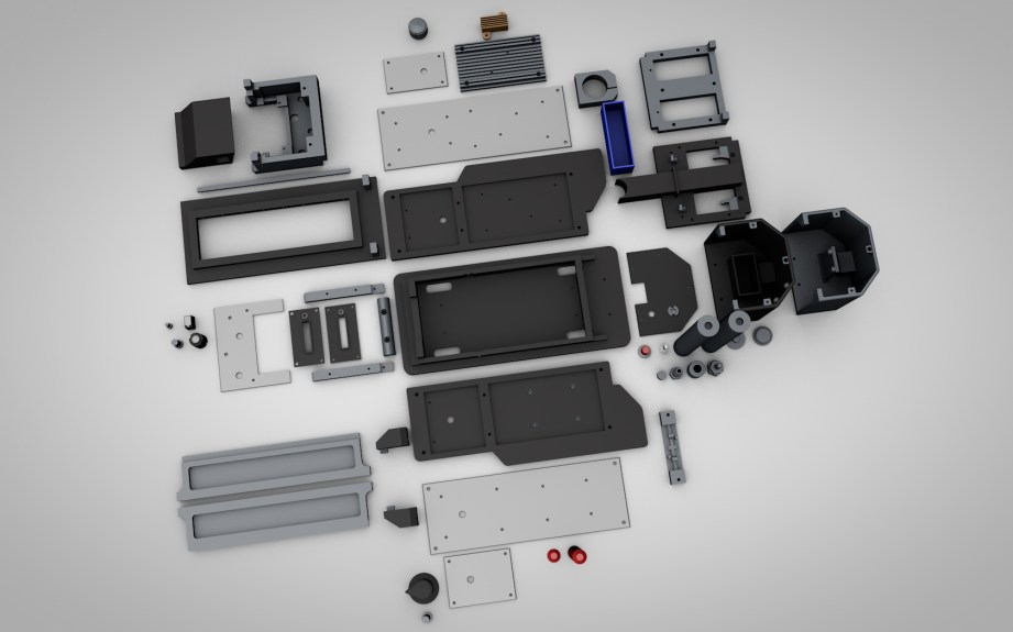
I modeled each individual part rather than glob them all together which is easy to do in 3D. I had seen other 3D traps that had all the plates, knobs, screws and other details print as one piece. This doesn’t allow for optimal printing orientation for each part and it makes finishing work like sanding and painting more of a challenge. By modeling everything separately and basing them on known material sizes, pieces of the trap can be easily swapped out and upgraded for the real thing when possible which is what I did for the Deluxe version.
My goal with the overall construction of the trap was to keep it as simple as possible while allowing easy access to everything.
My goal with the overall construction of the trap was to keep it as simple as possible while allowing easy access to everything. I had a car in high school that was designed in such a way that in order to change the timing belt, one of the mounts that held the motor in place had to be removed while the motor was held up by a car jack. I hate poor design like that and put extra effort into making the trap go together in a logical manner. This meant evaluating each construction step to ensure that the screws could be easily accessed, the screwdriver would actually fit in the available space, there was a place to mount each component, etc.. Elegant design is really hard but so satisfying when you accomplish it.
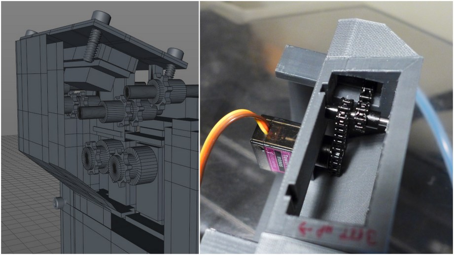
The biggest challenge in modeling the trap was figuring out the door mechanism. I still don’t know exactly how they worked in the films, but many times props will be shot at an angle or designed in such a way as to hide the actuating mechanisms. The rear of the doors are simply held in place with screws but the front mount to what I call the ‘wings’. This gave me some room to work, but it was very limited. Working in 3D allowed me to do various iterations until I found something that worked and fit in the available space. I can’t even imagine building each version for real, from scratch! I have great respect for machinist and other craftsman who do this all the time. In the end I used a dovetail on the wings so they slotted into the center console – we’ll cover exactly how the door mechanism works in the next article.
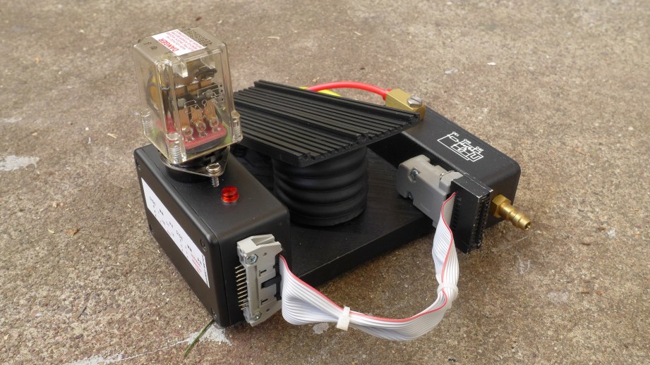
The trap pedal presented unique challenges as it had parts that simply couldn’t be 3D printed. The most distinctive being the electronics relay mounted on top – the original being a hard-to-find Italian relay no longer manufactured. The relay mounts into an 11 pin socket that is also used for vacuum tubes. The exact socket can also be hard to find, so I designed a three-part replacement. I found alternative relays that were a close match to the original and found that there were also 8 pin versions which widen the selection. I simply modified the 3D printed socket to make an 8 pin version to fit those as well. Other non-printable parts included the computer ribbon cable, tubing and pedal hinge.
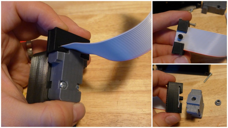
I did manage to 3D print all the ribbon cable connectors but had to devise a way for them to securely mount to the cable as it’s used to hang the pedal from the trap when mounted to your Ghostbuster uniform belt. I was very lucky in the case of the project boxes that are used on either side of the pedal as the manufacturer had the 3D models available for download. The real boxes are easy to find and cheap but the 3D printed versions have the advantage of already having all the holes in the exact right size and alignment for mounting all the hardware. Drilling all these by hand in the exact right alignment is a little more challenging, so to make things easier I designed a 3D printed template that folds around the box for marking holes. I was pleasantly surprised that the large 3D printed vector plate used for the actual pedal held up to being repeatedly stomped on.
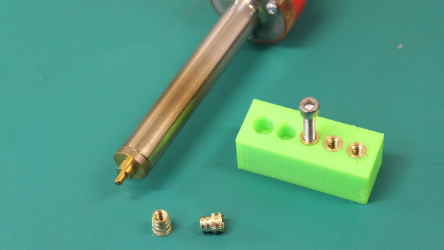
For assembly I had considered using heat-set threaded inserts which you can mount into plastic by pressing them in place with a soldering iron. The plastic melts around the heated insert and then solidifies around it, making a strong fastening point. These work great but with so many screws it also complicated assembly. There were also many spots where I didn’t have enough depth to accommodate the inserts. Based on the screws I had already selected, I used a tap chart which told me what size hole each screw needed to thread properly. I added a little bit to that number to compensate for printer inaccuracy and simply 3D printed every screw hole. Screwing right into the plastic works great as long as you don’t get carried away and overtighten anything.
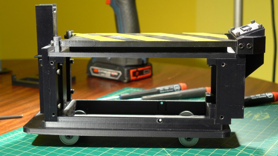
When printing parts on a filament printer you can choose how thin each layer is (resolution), how dense the interior is (infill, typically a honeycomb-like pattern) and how thick the walls are (shells). In some cases you may need ‘supports’ which simply hold up parts of the model that maybe hanging in empty space. The trap was relatively straightforward as most parts didn’t need elaborate supports or high infill. There were a few exceptions such as the handle which needed to be pretty strong, but even then I used only about 10% more infill. I was even able to do some neat tricks like printing scribe lines on the doors as a painting guide for the hazard stripes. By modeling all the parts separately it’s also possible to print everything in different colors to make a trap that looks pretty sharp right off the printer. With so many parts, this is a long print – clocking in at over 24 40 hours, but I like to think it’s worth the wait.
The final step was to export and organize all the files for printing and write an assembly manual. When I export parts I like to go the extra step of orienting them for optimal print quality. I also run every part through a mesh repair program (netfabb) to ensure there’s no problems that would cause the print to fail. It’s also a nice touch to name everything in a logical manner, for example, everything that goes on the right-side panel starts with the prefix ‘side_RT’. In college I had to take a technical writing course and I recall the professor telling us that you could make some nice money if you can write a good manual. I can see why – because it’s hard! My wife assisted me with taking over 100 assembly pictures for just the Standard Trap kit. You really have to step back and look at the assembly from a different perspective to ensure you don’t skim over or leave anything out.
The Ghost Trap is by far the most complicated project I have tackled and there were times that I was sure it couldn’t be done as I envisioned it. In the end I couldn’t be more pleased with how it turned out and I look forward to seeing the Ghost Traps that other fans will print and the improvements they will make. Once again we’d like to thank Dremel for sponsoring this project. The Idea Builder printer was a real workhorse, printing dozens of prototypes and finished trap parts. In the next column, we’ll get into the depths of the Trap and discuss electronics, door mechanisms and smoke pumps!
Download and print your own Ghost Trap and Pedal here.
Get hardware and deluxe upgrade parts for your own 3D-printed trap at Charlesworth Dynamics.
Watch Norm and I demo and discuss the Ghost Trap above.
Watch Jeremy Williams and I discuss the electronics of the kit!
Tested Builds: Fallout 4 Mini Nuke Kit, Part 1
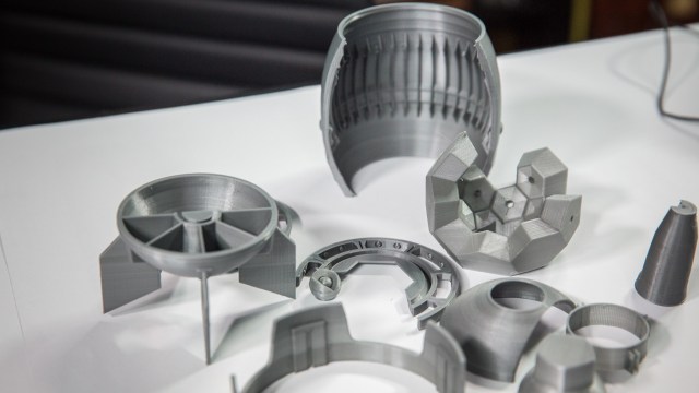
We kick off a new build this week, this time tackling a 3D-printed model kit designed by Jacky Wan. This Fallout 4 Mini Nuke model is a cross-section, showing off the beautifully imagined interior of the device and printed by Sean with our Ultimaker 2 desktop 3D printer. Frank is also in-house to assemble a kit and teach us how to paint it! (This first video is available for everyone–watch the rest of the build by signing up with the Tested Premium member community!
Episode 343 – The Long VR Minute Redux – 3/17/16

Hands-On with Oculus Rift’s VR Launch Lineup
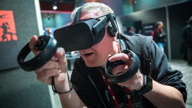
The Oculus Rift is shipping at the end of this month, and along with it will come over 30 launch titles that will be the first games virtual reality early-adopters can play. We attend an Oculus-preview event to play many of these games, preview more of Oculus Touch, and give our impressions about the wide-ranging experiences in this lineup. Plus, an interview Oculus’ VP of Product Nate Mitchell!
Shot and edited by Joey Fameli
Filming MythBusters with a Custom Chase Car Camera Rig
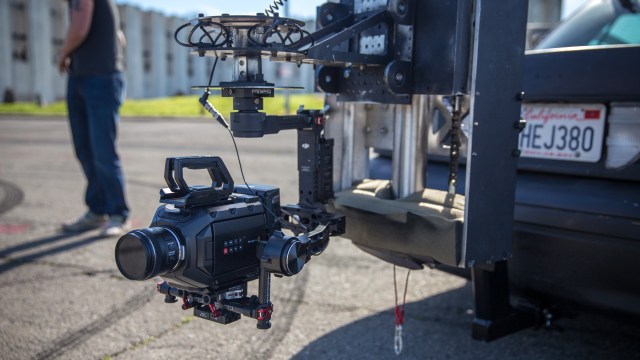
For the MythBusters series finale, the incredible wedge truck drive through 14 years of props was filmed with a unique piece of custom camera gear. MythBusters’ Director of Photography Scott Sorensen built a motion-controlled camera rig onto the back of an old police car, effectively turning it into a camera chase car! We go for a test drive and learn how the rig works with both custom and off-the-shelf technology.
Shot and edited by Joey Fameli
ILMxLAB: Star Wars and Cinematic Storytelling in Virtual Reality
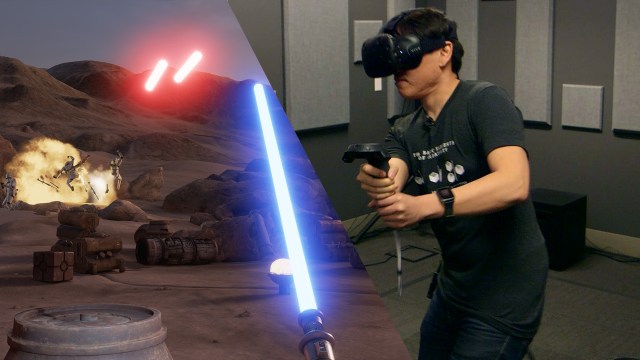
We were invited to Lucasfilm to check out the ILMxLab, the advanced research and development group inside the studio to experiment with virtual reality and other forms of new media. After playing the new Trials on Tatooine HTC Vive demo, we sit down with Lucasfilm’s CTO to chat about the potential for cinematic storytelling in VR and how Star Wars fans will experience new stories in the future.
Shot by Joey Fameli and edited by Norman Chan
Spotlight and The Big Short SPOILERCAST – Still Untitled: The Adam Savage Project – 3/15/16
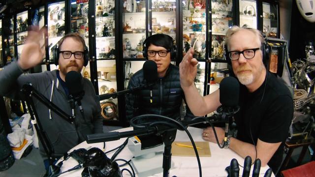
A double dose of SPOILERCAST this week as the team discusses two movies that won big at this year’s Academy Awards. We review and compare Spotlight and The Big Short, praising the performances in each and analyzing how the films portray historical events. Plus, a new book recommendation!
Ask Adam Anything #4: Time Management Tips
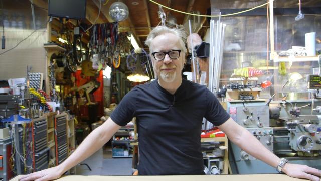
This week, Adam answers a question about how to avoid procrastination and manage the deadlines for multiple projects at once. If you have a question or something you want to share with Adam, post in the comments below! We’ll be back next week with another question answered!
Tested: Avegant Glyph Personal Theater Headset
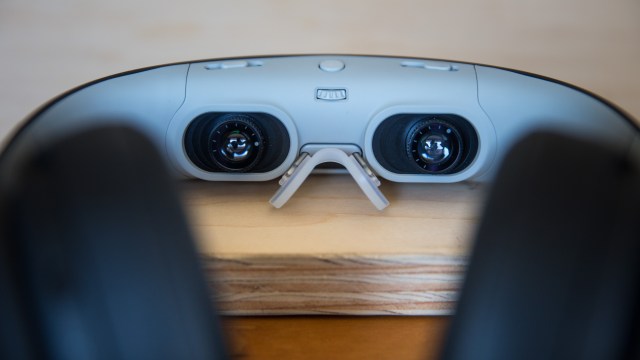
Norm reviews the Avegant Glyph, a headset that uses tiny DLP projectors to put a personal video theater on your face. It’s not a virtual reality headset, but has sensors for head-tracking for 3D and 360-degree video from your phone. But the best use of it may be with camera-equipped quadcopters.