


Gary joins Will and Norm to celebrate a milestone, catch up on the last few months, and discuss the implications of Facebook buying Oculus. Enjoy!
Inside Adam Savage’s Cave: What’s in the Mailbag?
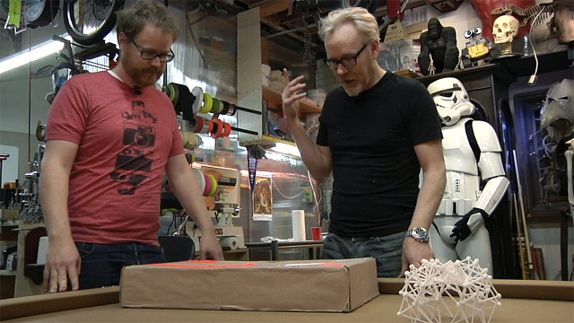
We stop by the cave, where Adam shares a mystery package he recently received from David, a Tested viewer from the Netherlands. After checking out its surprise contents, we geek out over the amazing packaging job too!
Photo Gallery: Star Wars Prop and Costume Exhibition


Premium: Behind the Scenes with Adam Savage at SXSW

We check in with Adam backstage at this year’s SXSW Interactive conference, where Adam talks about speechwriting and preparation process immediately after giving this year’s keynote address. Watch the full keynote here.
On Public Speaking and Dyson Spheres – 3/25/2014

Premium: Putting Together Papercraft Models
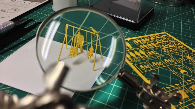
To give you a sense of how long it takes to put one of the Terada Mokei papercraft dioramas together, Norm builds part of one in real-time in his garage workshop.
Episode 199f – Virtual Everything – 3/20/2014

This week, Will, Norm, and Jeremy discuss SXSW and GDC. Topics include Bitcoin, the second Oculus Rift devkit, Sony’s Morpheus VR headset, CastAR’s latest prototypes, the latest Steam Controller, Google’s wearable computing platform, and more. We’re also joined live by a very special guest. Enjoy!
The Zoidberg Project, Part 9: All About Molding
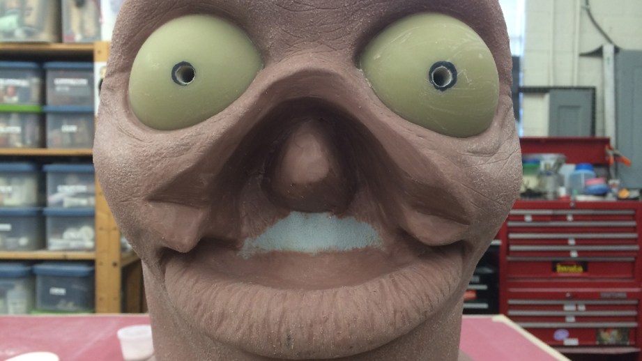
To be honest, I have been kind-of putting off creating the final mold for the Zoidberg project. It’s probably a little bit out of fear that I’ll get it wrong; once the sculpt is molded, there’s very little I can do to change it. But, I’m finally doing it this week.
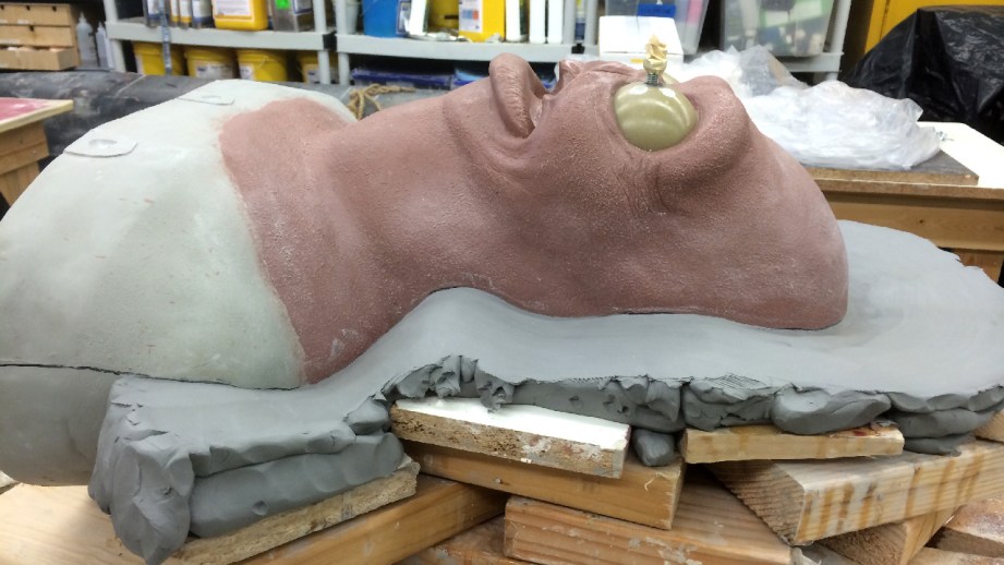
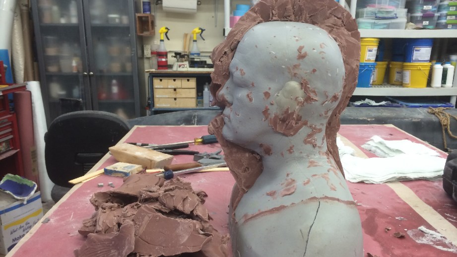
Molding the Zoidberg head with his tentacles attached would not be the best way to do it. There is too much detail on the inside of the mouth that is unfinished. I would never get the clay out of the long tendrils, it would be tricky to core out the tentacles for the animatronics to fit in, and would be a pain in the neck to cast up in foam latex–just to name a few possible issues. So the first thing I need to do is cut his upper mouth off so I can mold the head in two separate pieces.
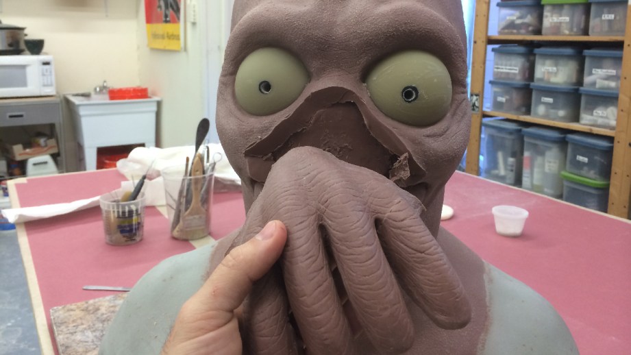
I’m going to be as delicate as possible and try not to disturb any of the major forms. Once the upper mouth is fully removed, I want to clean up the spot where the two pieces of the sculpture would meet up. Kind of like making a blending edge on a prosthetic appliance. This will help when the final tentacle part is reattached.
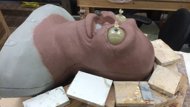
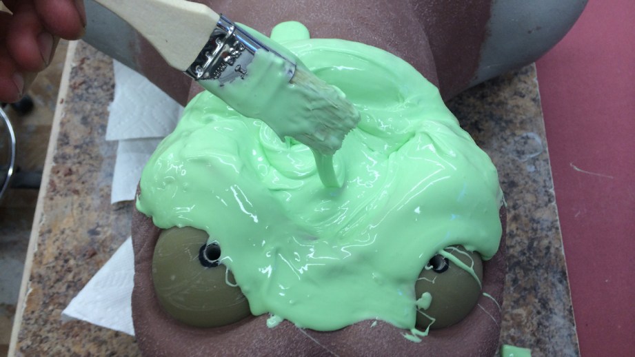
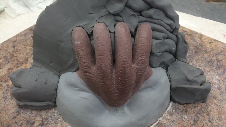
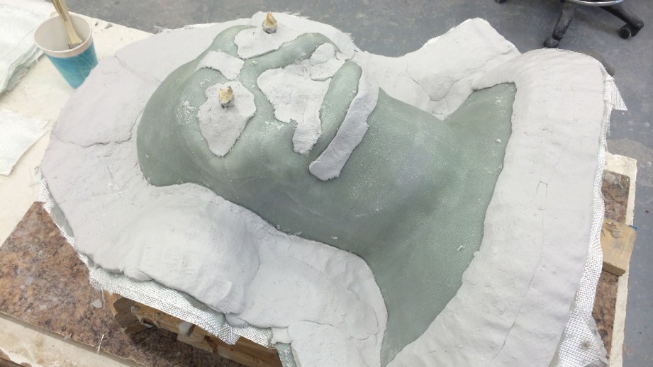
Once this is all cleaned up, I use some Body Double SILK silicone to mold the area of the face where the tentacles will attached. This will give me an accurate reproduction of that area to sculpt the tentacles onto. To do this, I just mix up a small batch of the silicone and carefully brush it onto the sculpture, being careful so I don’t scratch up the surface. I’ll apply two coats of this silicone, then I’ll take some plaster bandages and carefully lay them up to make a rigid shell. This will keep the silicone in the correct shape after I take the mold off.
Next, I need to take the Body Double SILK mold and fill it with some hydrocal gypsum to make a fast positive of the mouth area (the silicone mold was a negative impression) so that the removed tentacle section can be blended off on to. At first the whole negative-positive terminology might be a little tricky to grasp, but if you just remember that the negative is a void, and that the positive is an addition of space it can be easier to understand.
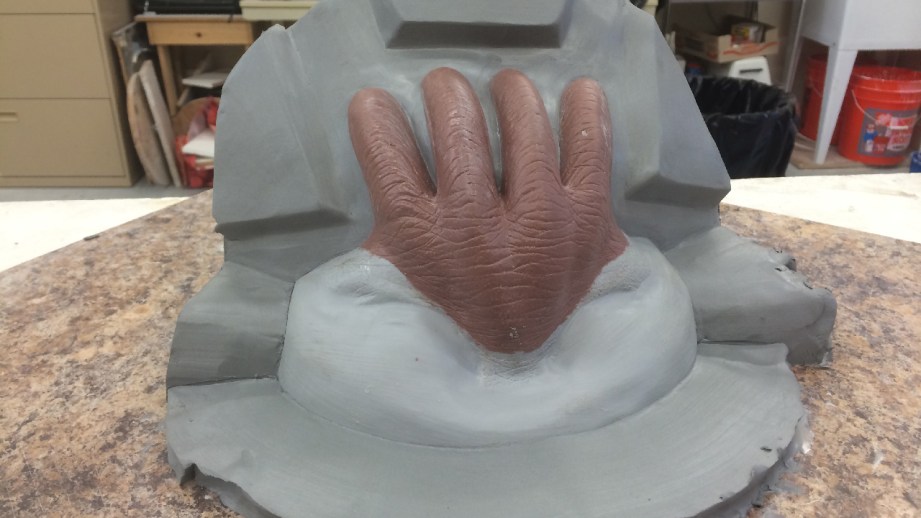
I want to add a little bit of extra land onto this positive so that it can be clamped or bolted closed. ‘Land’ is a term for the extra space outside of the area that you are using on the mold. In this case you can probably also consider it a flange.
Now, I know that these tentacles will be a two-part mold, so I want to make sure that the positive is laid out correctly to make all the parts fit together easily. I also know that I will be adding some sort of core inside this section to create a space for the animatronics. In addition, I want the pieces to all bolt together easily.
Once I have the material added in water clay (EM-210) I’ll make another mold of this, in regular Body Double silicone. The reason I used the Body Double SILK on the first part is that it has extra ingredients in it that allow it to release from skin better, and I figured that it would release from the sculpture better and minimize any damage and cleanup. Since this mold is less fragile, I’ll use the regular Body Double. Just like with a lifecast, I’ll apply two layers and then back it with plaster bandages. Except this time I ran out of standard body double, and did my second coat with some left over body double silk.
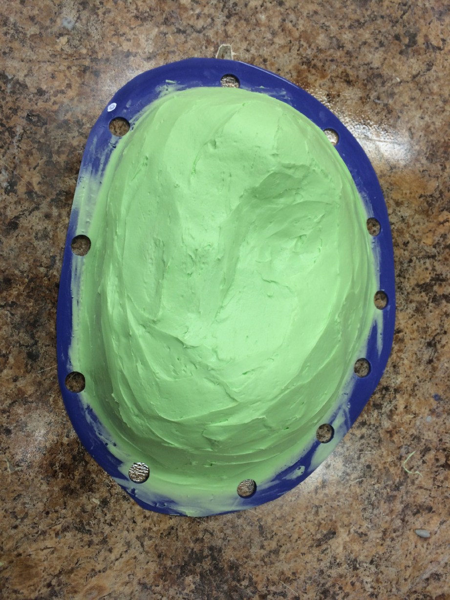
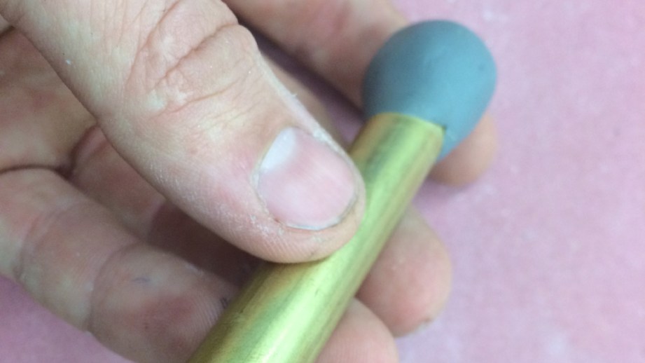
When I make little brush-up molds like this, I leave the run off on the table and trim it back to a sort-of flange, then cut little holes in it to register into the bandage jacket with a little tool that I made out of some brass stock, and a little plumber’s epoxy on the back side to create a handle.
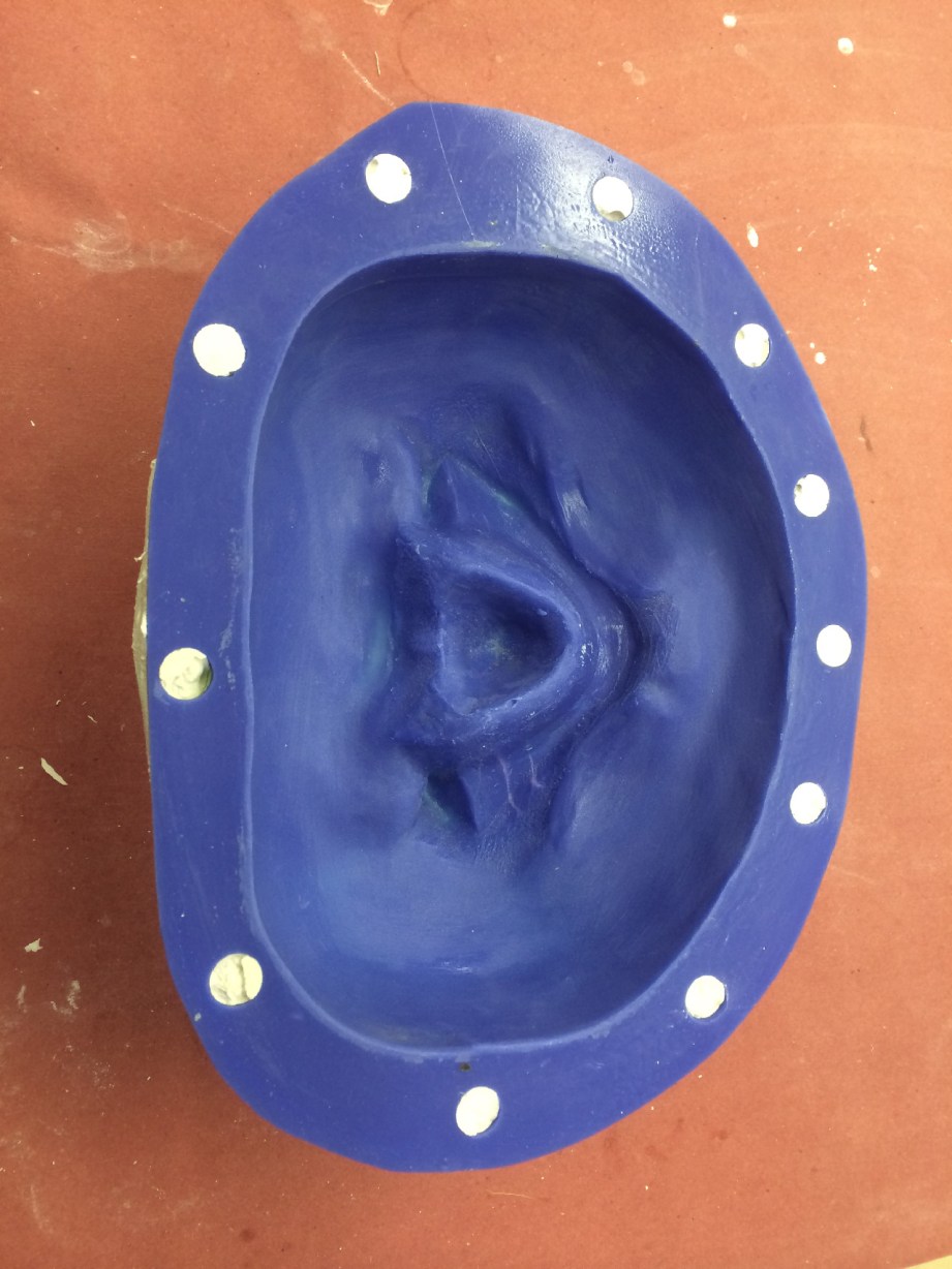
Then I want to clean it out and cast up an epoxy positive, exactly the same way I did the epoxy positive of the head. Two layers of EpoxAcote GREY, two layers of 10 oz cloth with EpoxAmite 102 MEDIUM. Next, some Free Form AIR epoxy dough and then two more layers of cloth with EpoxAmite.
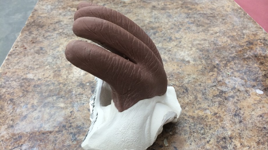
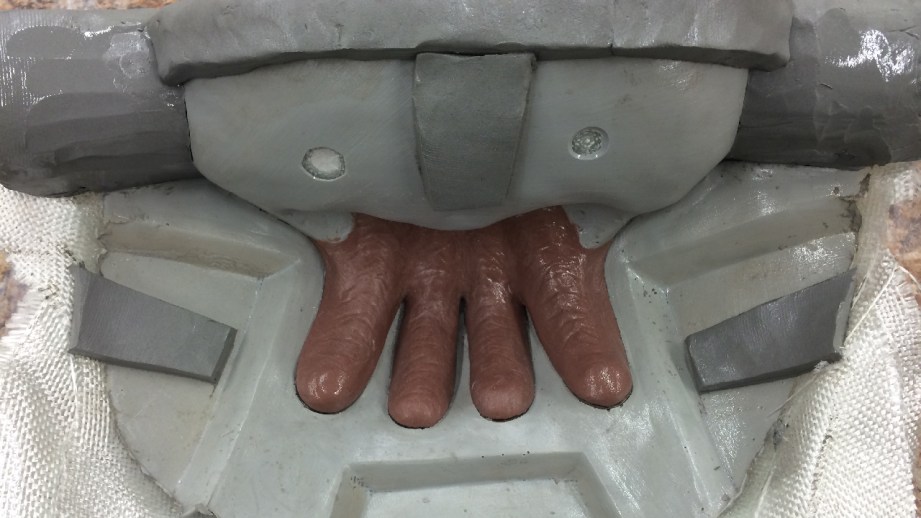
Now that I have this all made, I can place the clay onto this epoxy positive and clean up the sculpture. I can repair any damage and sculpt the edges to blend onto the rest of the head.
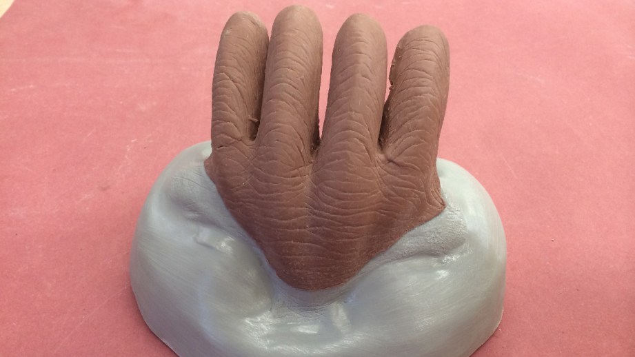
I also want to straighten out the tentacles and spread them apart a bit more. This will help with molding and make it easier for me to clean up all the detail.
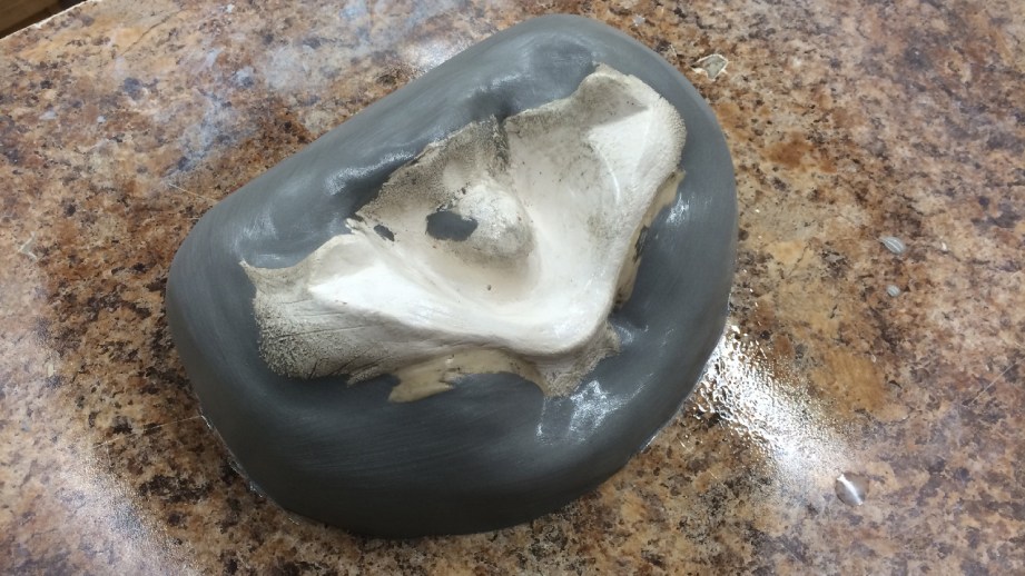
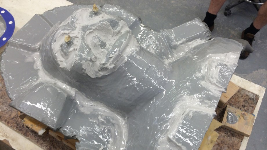
With the sculpture cleaned up, I can finally get to molding it. I’ll spray a couple coats of Crystal Clear acrylic spray onto the clay as a sealer, then mark my dividing wall. This mark works as a target when making the wall out of clay.
Without a mark, it’s easy to get off track and not place the wall in your desired spot. I’ll use water clay for this (EM210) just like I have done on the arms before. Once the clay wall is up, a few more coats of Crystal Clear acrylic, and a few heavy coats of Ease release 200…then back to the same ‘ol epoxy workflow. Two layers of EpoxAcote GREY, then five layers of 10 oz glass cloth laminated with Epoxamite 102 resin. You don’t always need to put in the dough layer on the flange, it just helps with rigidity and accuracy. For this little mold, I don’t think it’s necessary. When this is set the next morning, I gently remove the clay wall, and clean up the clay residue with some water in a spray bottle and a soft brush. I’ll add a couple of pry points, to make the mold easier to open, and repeat the whole epoxy process again.
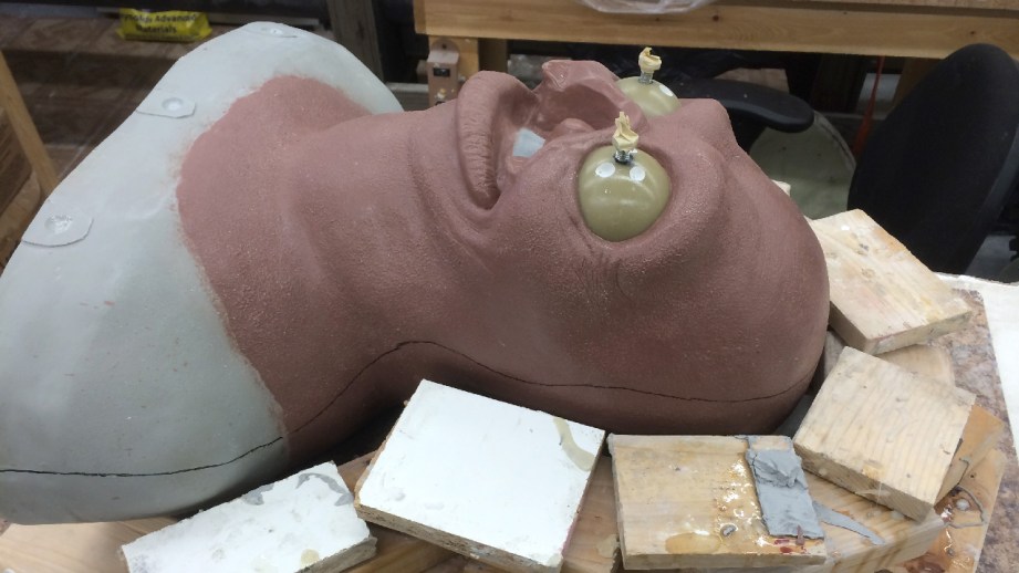
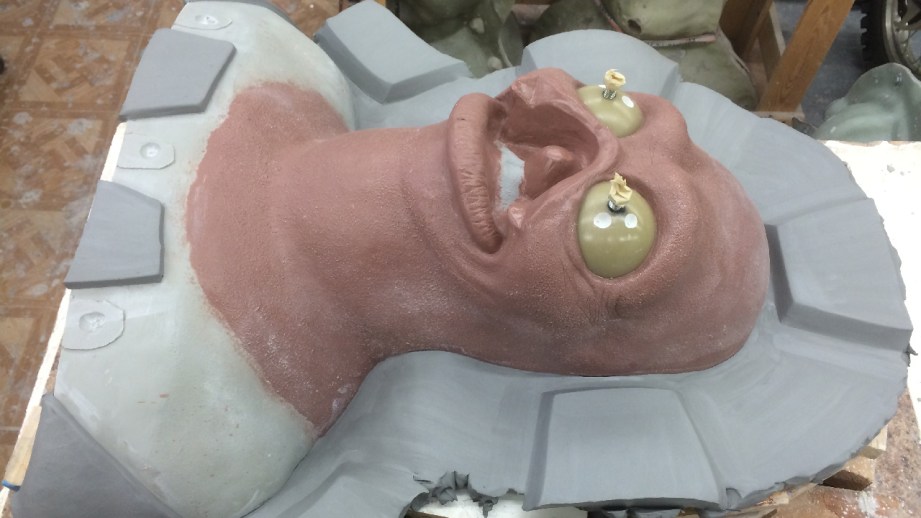
Molding the head will be the same process, only scaled up. I apply a few coats of crystal coat for sealer and mark the dividing wall. I want to lay down the sculpture for this part, it will just make it easier to lay up if it’s laying down. I have a few scraps of foam laying around that I’ll use to cushion the sculpture when I lay it down. Then I have a bunch of scrap pieces of wood that I’ll place around the sculpture to create a sort of scaffolding just a little shy of the parting line. Then I can bridge those pieces of wood with a bit of plaster bandage and lay water clay on it to make the parting line.
Usually when I do these clay walls, it’s a few steps to get it all nice and smooth. I start roughly putting in the clay, sometimes in slabs, sometime in wads that I just form in my hands. Then I take any number of spatulas or serrated scrapers to even out the surface, not worrying about the edge closest to the sculpture yet. This gives me a good general surface to work with.
I take a small spatula and clean up the part closest to the sculpture, again not necessarily worrying about the tiniest bit up close to the sculpture–this pass is mostly to refine the line of the wall, and make sure it comes right up the line that I marked.
Once a pass is done, I’ll take a rubber-tipped tool and a little water and run that up against the sculpture to get the finished parting line. If used gently, the rubber tool won’t nick up the sculpture. To finish the wall off, I’ll sometimes take a makeup sponge and some water and wipe it down. Then using my clay cutting board, I’ll cut some slabs of clay and make some registration keys. I prefer big trapezoidal keys for this kind of mold.
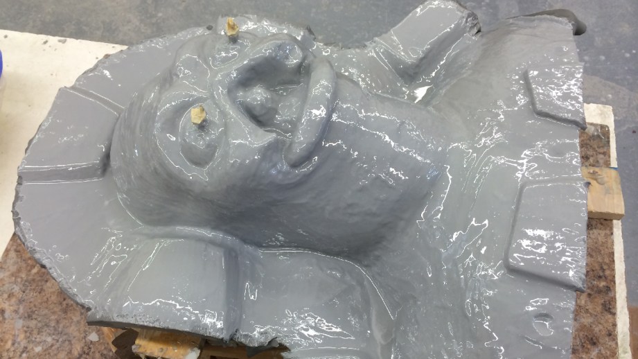
Topping it all off with a few coats of crystal clear to seal it and a few heavy coats of Ease Release 200.
Now, back to the tried and true steps of epoxy. I’ll start with a batch of epoxacote grey. It’s a 100-15 ratio, and I’m doing a 500g batch. That means I’m going to use 75 grams of catalyst. Epoxy is like any other material: it works best when mixed in the proper ratios. I don’t recommend adding more catalyst to speed up the process, as too much catalyst will change its dimensional properties (eg. it may shrink more) or heat up too much, or not cure correctly.
I like to use an air hose to blow the surface coat around as I brush it into the details. I also sometimes use a hair dryer as well. The small amount of heat will drop the viscosity and help get rid of small air bubbles or voids where the surface coat didn’t get into the detail. You have to be careful, because with clay like Monster Clay, a small amount of heat could soften the surface and mess up the detail of the sculpture.
This layer will sit for about 45 minutes, or until when you touch it, it will be slightly tacky but not stick to your finger or pull away. Then it’s safe to do another layer and wait another 45 minutes. During this dow time I like to prep my glass cloth and dough for the rest of the mold.
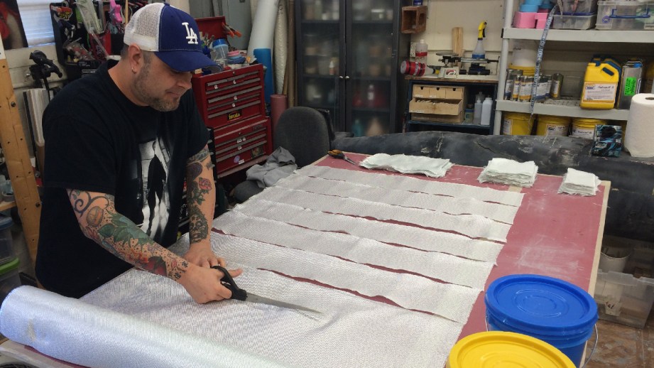
When using glass cloth, it’s better to use the largest pieces that you can. For this kind of mold, I usually prep out three sizes of cloth. Small (3 x 6) strips to work into detail and compound curves, 6 x 6 squares, long 12 x 6 strips for the flange layers. I’ll use a bit of freefrom air in the next step, so I will pull out a golf ball-size of the A part and the same of B part, and set them aside. For the flange, I’m going to only use a thin layer of Dough, so I’ll pull out a couple softball size portions of a and b, and set them aside also.
One of my favorite things about epoxamite is that is comes in containers that you can get metered pumps for. This means that one full push of A and B will be the correct volumetric ratio to work with. I have noticed that the pumps can sometimes be a little lean on catylist, and I don’t know if that’s my error or not, but I like to always use three or more pumps of material, that way any inconsistency of catalyst will be a smaller overall percentage. If I ever need to do smaller batches, I like to weigh them out because of this.
I time all of this prep to be done when the second layer of surface coat is to the tacky phase.
Now comes a bit of timing. I mix the two golfball-size portions of freefrom air, and set them aside, then I’ll take a four pump batch of resin and coat the whole thing. Using the small portions of dough, I’ll fill in any sharp corners or deep detail. My goal isn’t to use much of the doing, but only just enough to help the glass cloth transition any sharp changes in direction, and tiny corners. The dough has little compressive strength, I only really want to use it for sandwich construction between layers of glass. But it comes in handy for small things to fill a bit.
Once this is put in and smoothed out, I can start laying my glass. For the first two layers I’m not too worried about size or direction of the glass, only that it’s getting two even layers of coverage. Once I have these two done, I’ll mix the softball-size portions of dough by kneading it out on a sheet of freezer paper or wax paper that I have taped to the table. I’ll leave it smushed out into a thin section while I’m working with it because in a large mass,, it will heat up and kick off quicker.
I like to pinch off handfuls and press them between my hands to get close to the desired thickness, then lay it onto the flange. I only want about 1/4-3/8″. I don’t think I need more for this kind of mold, and how I’m going to be using it. When I do molds that have longer production runs, I’ll make the flange 3/8-1/2″ it just helps with handling and rigidity when you are running molds often.
As I press sections in, I take care not to trap air under, or I between new material. sometimes taking a tongue depressor or paint stuck and pressing it flat into the dough to pack it down.Once this is done all along the flange and a strip at the base of the torso, I’ll go ahead with my last two layers of glass. Make sure to we’d down the dough with some a resin batch, as it will help with taping the glass and with adhesion. Again. I try and use the largest pieces of cloth, and alter the direction of the weave and where they overlap. It helps make the layers stronger to vary these things.
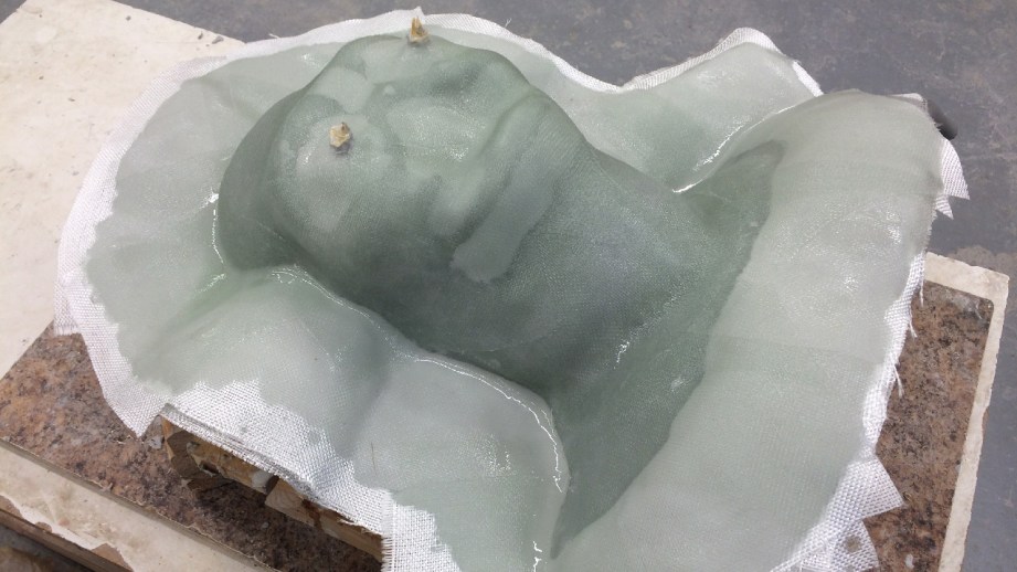
Once two layers are done, I can let it sit overnight. First up the next day is to carefully flip the mold. I don’t want any of the wood blocks to ding the yet to be molded side of the sculpture. After cleaning off the water clay like before, I’ll add some small pieces of clay for pry- points to aid in opening the mold, and do the whole process over again. Crystal clear, Ease Release 200, two layers of epoxacote, two layers of glass, a bit of Dough on the flange, and two more layers of glass.
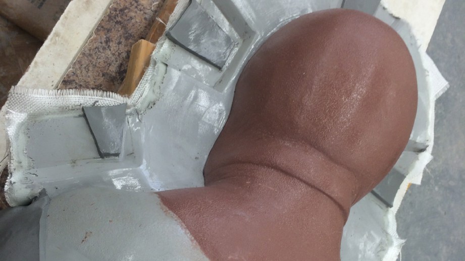
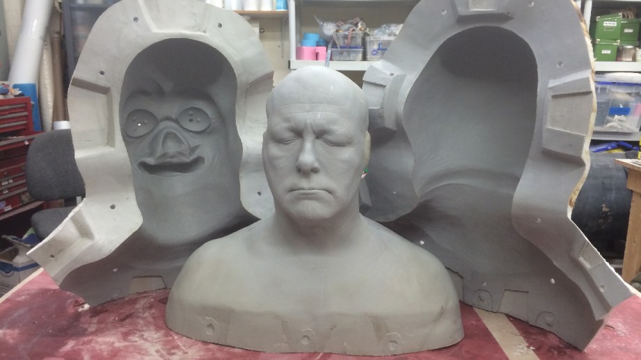
Now all that’s left is to trim these molds, crack them open and clean them out.
I like to use a reciprocating saw with a general purpose 8/12 TPI blade to trim my molds. Any fewer teeth and it gets chewed up, and more teeth, and it takes forever or burns up the blade. Because I made the clay wall about 3″ wide, I know I can trim off the last 1″ of the wall without getting too close to the sculpture. Once they’re all trimmed up, I’ll pull out a couple of large screwdriver or pry bars and slowly work my way around the mold and pry with slow even pressure. You don’t want to force a mold open, as it might crack.
The next step it to order a pizza and crack open some beers while you bribe your friends to help clean out the molds. Sometimes this takes forever, because you have to get it out of all the little nooks and you can really only use wooden tools. I try and avoid using anything metal, as it can scratch the the plastic surface of the mold. With monster clay, you can warm it up a bit to soften it, but I generally avoid using heat to aid in removing the clay. If you try and melt it out, it will just leave a layer of molten clay stuck on the surface of the mold that you will have to scrub out with solvent later. Which brings us to the next step. After you get as much as possible out, you need to use a little solvent to clean the small amounts of residue. For Monster Clay, Naphtha seems to work best.
Phew. Now the main molds are done. Next time, we will deal with adding t-nuts, making some core-inserts for the animatronics, and running the foam latex skins! We’re getting close!
Thanks to Iwata-Medea and Smooth-On for providing materials and sponsoring this project.
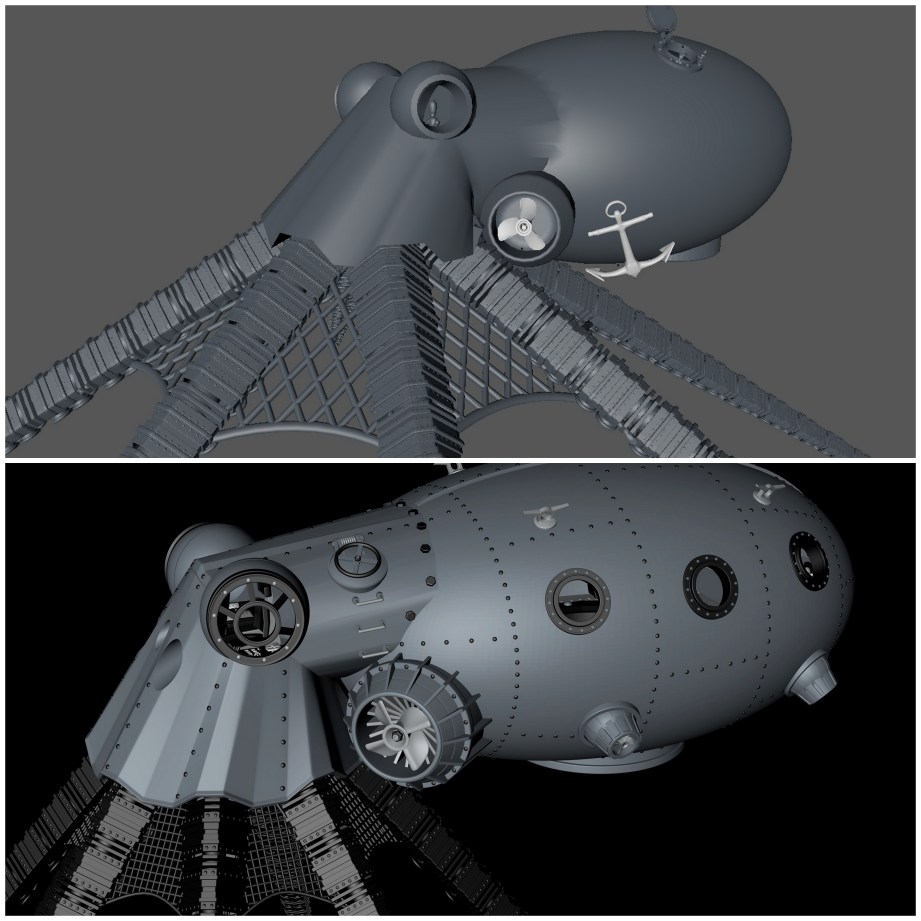
Bits to Atoms: 3D Modeling Best Practices for 3D Printing
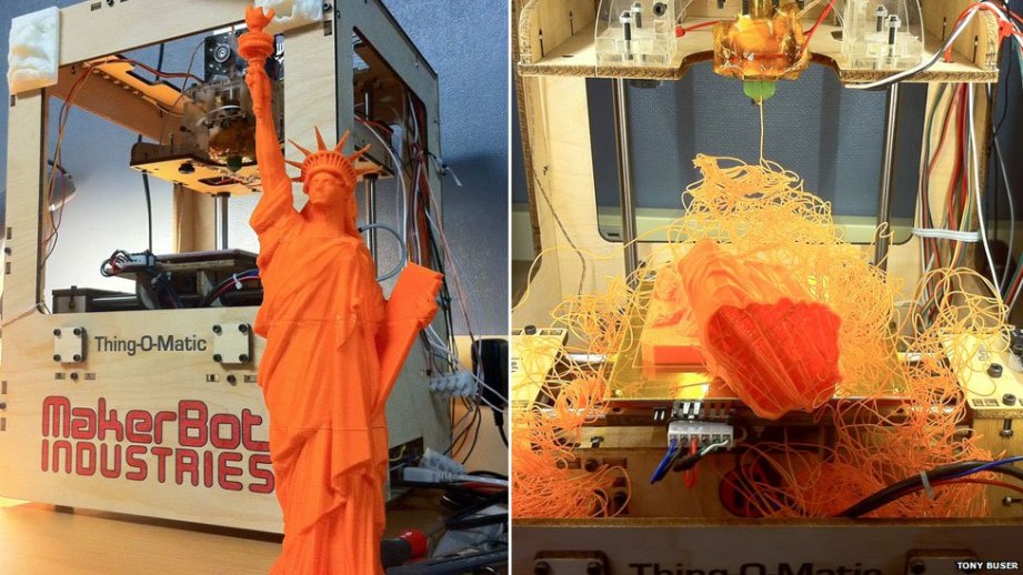
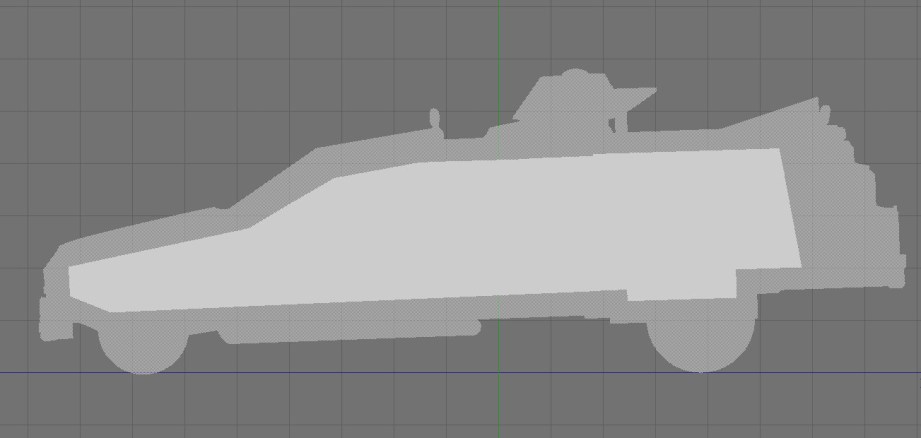
So you’ve managed to build your first 3D creation using modeling software. You send it to the printer and it comes out looking like something sent through a cosmic spatial anomaly. What the heck happened? Building your model on the computer is just the first step to ensure a proper 3D print. Today, we’ll go over best practices for modeling and how to prep those models for a good print.
Neatness Counts
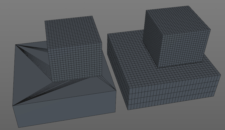
Taking the time to sculpt a neat, clean computer model will prevent headaches down the road. This is particularly true of polygon models where deleting an edge, face, or vertex can quickly make a model unprintable. Using boole operations (adding and subtracting part together) is often used while building models, but can lead to messy models since two pieces of geometry are being combined or subtracted from one another.
Sloppy modeling can easily occur just in the process of figuring out how to build something. I will often build a quick, rough model to work through the layout, what parts need to be made, and how to build them. I will rebuild the whole thing as a much cleaner model based on the rough version. One of the best pieces of advice I got from my modeling mentor is, ‘don’t be afraid to rebuild something‘. It sounds like a drag but rebuilding a model from scratch always goes quicker than the original and it will be a cleaner model, using what was learned from the first version.
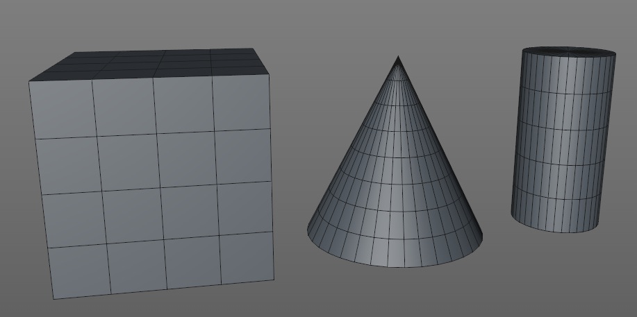
If modeling with polygons, it’s in your interest to keep the mesh in quads (each face is four-sided) and avoid “n-gons” (in modeling, any polygon that is not 4-sided). Modeling with quads makes adjusting the model much easier, whereas n-gons will kind of mess things up. In general, any modeling program will make it easy to model in quads since any primitive (cube, sphere, cone, torus, etc) created will automatically be made out of quads.
A good housekeeping rule it to name everything upon creation. If there’s ten different cubes that were used to make ten different parts on your model it will be tough to tell them apart if they’re all listed as ‘cube’.
Size Matters, Somewhat
Due to limitations of both the printer and material used, you must pay constant attention to wall thickness, size of details and overall size of the print.
Due to limitations of both the printer and material used, you must pay constant attention to wall thickness, size of details and overall size of the print. If you make a wall too thin or detail too small you will most likely have some holes and breakage on the printed model. This can be tricky considering that not all modeling programs let you build in a particular unit. Some programs may list a circle as being 10 in diameter, but what is the unit of measurement? That’s the glory of digital design; it doesn’t really matter since the model can be scaled up and down almost indefinitely. But if the material you are printing in needs a minimum wall thickness of 1mm, then units become important.
In this case, I will generally decide that 1 unit = 1 cm or 1 inch, etc and model accordingly. Even having done this, you may export the STL and rather than 10 cm long your model is 100 cm long! It all depends on how your program exports, some will allow you to specify the units, some won’t. Regardless, once the STL is opened in the slicing program you should be able to scale it to the correct size.
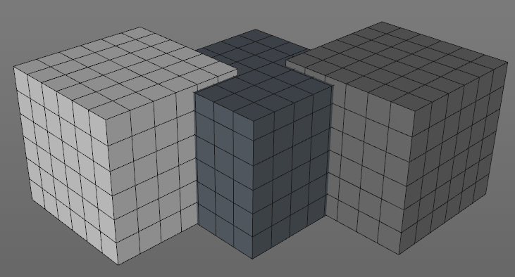
A helpful trick is to create a reference cube to ensure proper scaling. If I decide to model in centimeters I create a 5 x 5 x 5 unit cube and subdivide it 5 times and know that the cube should be 5 cm when printed and each subdivision is 1 cm. During construction I will use the cube to verify distances that might otherwise be hard to measure. When exporting the finished model I will export the cube as a separate object and then bring them both into the slicing program. I can select the cube and easily see if it’s the correct size and scale the cube and model up and down as needed. When done, the cube is deleted and the main model should be at the proper scale.
Subdivide and Conquer
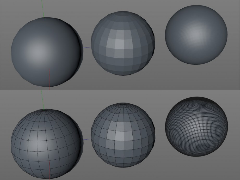
As we have discussed before, 3D printers only print pure geometry, so you need to make sure your model is smooth enough to print well. If you are using a polygon modeler remember to turn off any rendering shaders since they fake smoothness on the screen.
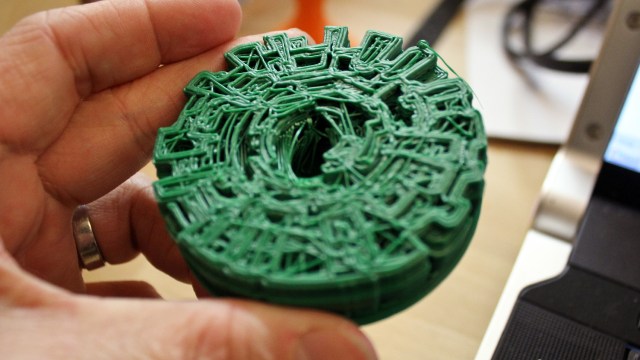
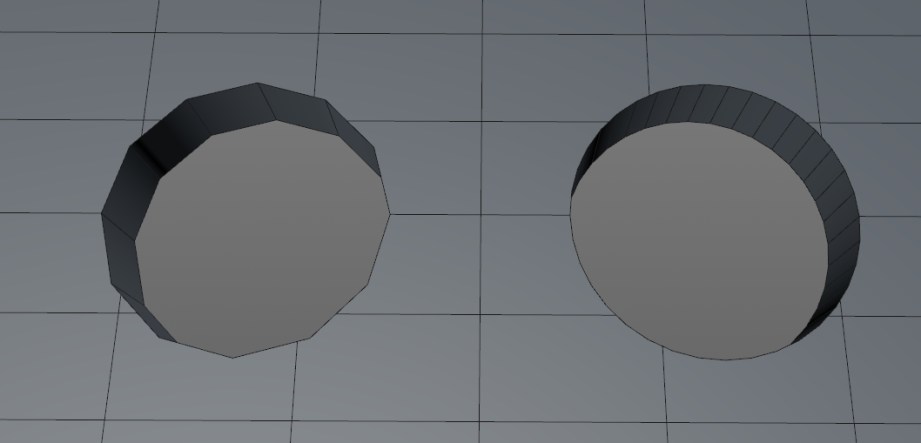
If your model looks chunky on-screen you will need to add more subdivisions which means adding more polygons. How many subdivisions to add is a tough question since the answer depends on multiple factors. A sphere may look a little blocky on screen but maybe it’s only 10 mm in diameter when printed so, at that size, it will probably print just fine. It’s also possible to go to the opposite end of the spectrum and have too many subdivisions. Going crazy with subdividing will bog down your modeling program, the STL export, the mesh repair program, the slicer and maybe even the printer.
A good example of over-subdividing is making small holes on a typical home FFF printer. If you add enough subdivisions to make a perfectly smooth hole the printer won’t be able to properly translate so many small moves. It’s better to use a lower edge count which will produce a smoother printed opening.
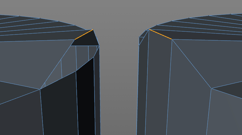
Adding subdivisions to something like a sphere is pretty straightforward; add more divisions, sphere looks smoother. But what if you want to make a cube with rounded edges? I could subdivide the heck out of it and it will still look like a cube–this is where you need a subdivision surface, AKA “subD” modeling–not to be confused with regular subdividing. SubD modeling is kind of the polygon equivalent of modeling with NURBS since it’s good for smooth organic surfaces but doesn’t take as much computing power. Adding a subD modifier to an existing model will add subdivisions AND a smoothing algorithm, similar to the render smoothing, but in this case the actual geometry is smoothed.
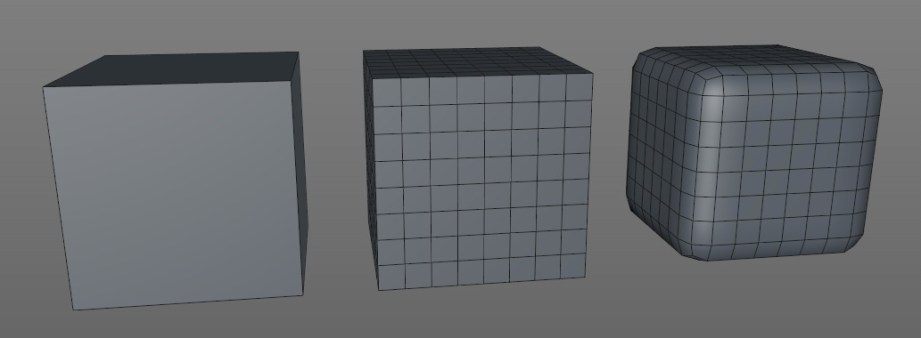
Like NURBS, subD modeling uses a ‘cage’ to control the high-resolution model and the subdivisions can be adjusted at any time. The cage is basically the low-poly model that you applied the subD to. Trying to adjust a high-poly mesh would be a nightmare, so by using the low-poly cage we can easily make changes. The catch to subD modeling is it may smooth too well and you will have to add in additional ‘edge loops’ to more clearly define edges and features. This is where modeling in quads is really important since a model not in quads is very hard to properly modify as a subD surface.
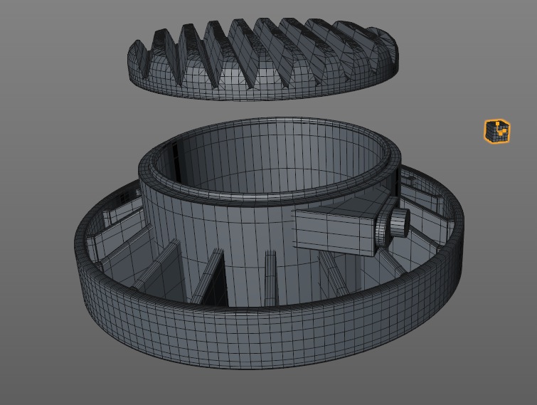
Boole-Ya!
Booling uses add, subtract and intersect functions to combine geometry in different ways. It’s an important feature for modeling and for 3D printing in particular. You can easily make a model by taking a bunch of primitives and sticking them together and it will look okay and render okay, but probably won’t print well–if at all.
The problem is mashed together parts have hidden geometry that is inside the other parts, but still gets sliced and printed. This can cause problems with the slicing software–making it take longer to finish, or even crash–and the resulting model will often be messed up, have holes or weird geometry problems.
Even if the model slices properly it will take longer to print and use more materials since all that hidden geometry is being printed as well. In the long run it’s far better to suck it up and combine all the parts into one shell using the boole function.
If boole operations are spitting out funky geometry, make sure neither object has typical geometry problems (see repair section at end of article). Good news for CAD users, you should get clean, problem-free booles almost every time.
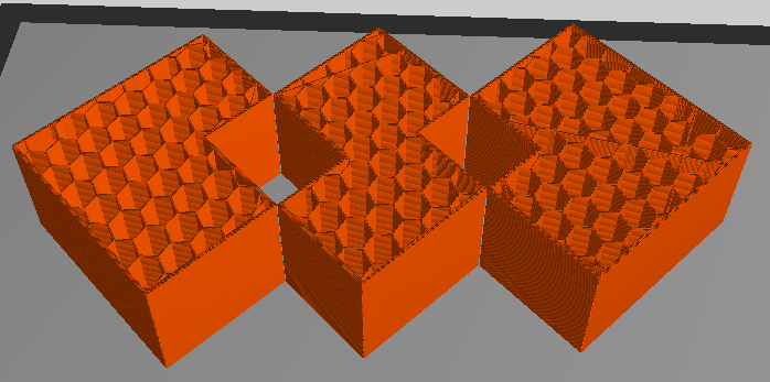
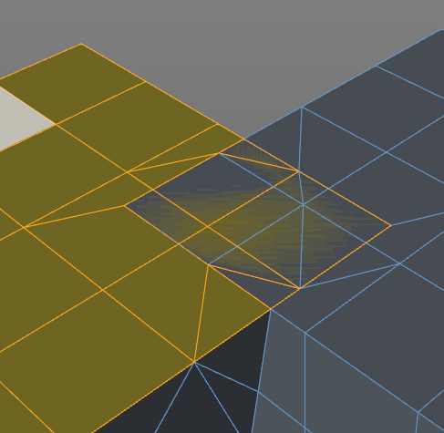
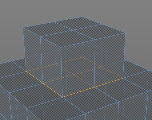
The Shell Game
Shelling is mainly used to cut down on weight and save money when printing on machines that use a powder material such as 3DP, CJP or SLS. As you may recall, the powder printers use the loose powder in the print bed as support material. If the model is hollow, the support material from inside the model can be removed and you won’t be charged for it. In some programs you can simply use a hollow function, specify the wall thickness and blamo! it’s done. Unfortunately, most programs don’t have this function, so you have to do it manually by creating an inner shell.
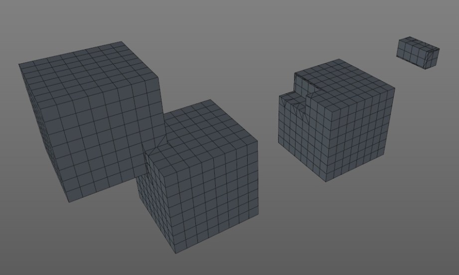
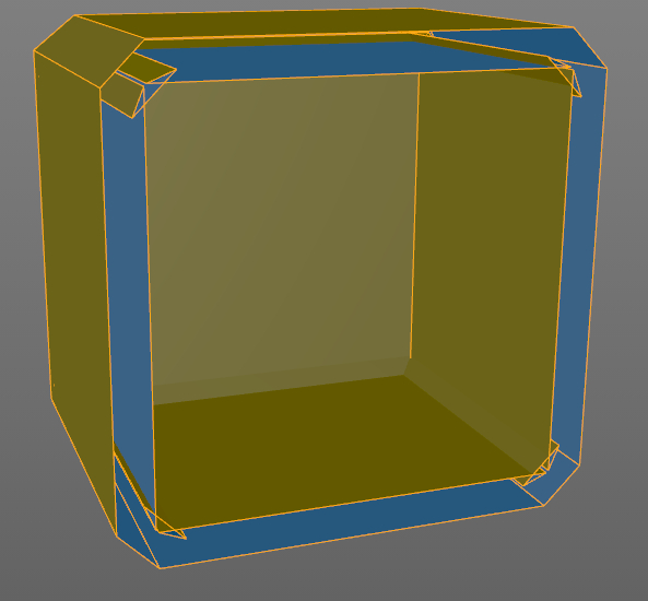
First, you want to boole together most of the larger pieces which make up your model. This will create one continuous shell and if you’re lucky you can select the whole thing and extrude the surface inward, basically making a duplicate shell inside the original, like we did in the MintyBoost video. Unfortunately, this does not work for a lot of models, so keep a close eye on the inner shell when you try this. If geometry starts to intersect itself or freak out, it’s not going to work.
The more tedious option is to boole the entire model together to make one large shell and build the inner shell manually. This can be done by putting a simple primitive, such as a cube in the center of the model and carefully extruding and adjusting it outward to create a shell. It’s helpful to use the wireframe or x-ray mode in the side and top views so you can see inside. Remember that reference cube we made? Use it to eyeball the proper wall thickness for the shell, it doesn’t have to be pretty or even super precise since it’s on the inside and will never be seen. The last step is to combine that cube with the model and then cut escape holes for the support material.
If you want to see what this gains you, upload the same model, one solid and one hollowed to Shapeways and get a quote for strong and flexible material; there are savings to be had.
This method won’t gain you anything on a home FFF printer since you can specify wall thickness (shells) and fill percentage in the slicing program. I will often have multiple versions of the same model tailored for specific printers.
Don’t Worry, She’ll Hold Together
The final step is to check your model for potential issues which may cause print problems. Some flaws are easy to identify, and some can be really difficult to pinpoint and fix. Here are some typical issues:
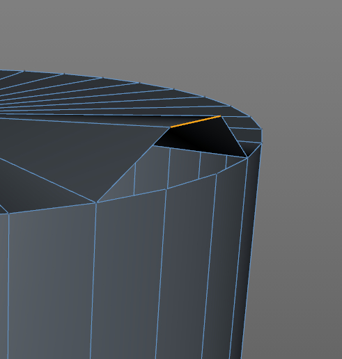
Not watertight – this shouldn’t happen with a CAD model, but a polygon model needs to be completely sealed–so if you were to theoretically fill the interior with water, it won’t leak. This can be an obvious problem, such as a large face that’s missing, but is much harder to find if it’s a very small face. It’s also possible for an object to look completely fine and have an edge that’s unattached. Using an ‘optimize’ or ‘mesh cleanup’ command will often fix this problem and/or a mesh repair program such as netfabb (see below).
Non-manifold – this is kind of an M.C. Escher, impossible geometry problem where more than two faces of an object share the same edge or vertex which is bad and will cause print errors. You may have to rebuild a portion of the object to correct this problem or use mesh repair software.
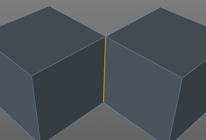
Laminate faces – this is a non-manifold problem where multiple faces overlap each other and can be really hard to spot. This often happens with the boole function when faces overlap each other and you may just have to delete a suspect area and fill it with a new polygon.
Internal faces – this often happens with extrusions if you have an ‘add caps’ function turned on. Rather than making a hollow extrusion, an interior cap is added. I do this ALL THE TIME and it can be maddening to diagnose and may cause print problems. Try using wireframe mode or go inside the object to look around and delete the face.
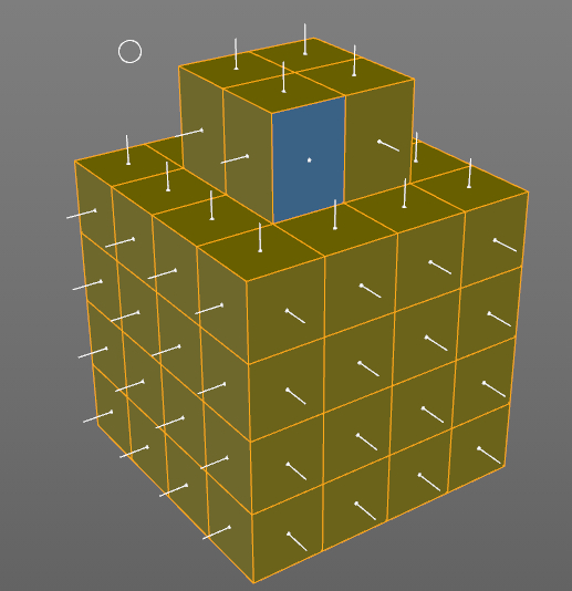
Flipped Normals – What? Each face that makes up an object has a ‘normal’ which defines what is the inside and outside and sometimes they get turned around. SketchUp is kind of notorious for doing this, but most programs will show flipped faces in a different color and/or have a little perpendicular indicator on each face. There should be an option to ‘flip’ or ‘align normals’ to solve this problem and mesh repair programs will usually fix this as well.
Other than what I quickly mentioned for each problem, some possible fixes from within the modeling program are ‘optimize’, ‘mesh cleanup’ or similar functions that will look for unused vertices, non-manifold edges and sometimes flipped normals and fix them. There may be a be a ‘tolerance’ option for combining vertices which are very close to each other. It basically tells the optimize function to combine vertices that are less than X units apart. This can be helpful for fixing watertight issues but can also combine vertices that it shouldn’t and cause new geometry problems. You may have to fiddle with the tolerance setting to get the proper results.
After doing what you can within the modeling program, it’s time to export as an STL and run it through a mesh repair program. This is a must. It doesn’t matter how carefully the model was built or how clean it looks, there are often small, hidden imperfections that will cause print errors. Some software choices are:
Netfabb is my go-to repair software that will fix most problems automatically. There is a free basic version and a cloud version which I suggest to newbies since it is completely automatic and will actually fix more problems than the desktop version. A big advantage of the cloud version is that it will take multiple parts and combine them into one mesh–the free desktop version will not. You can try having the cloud version do all of the booling for you, but be sure to check the model thoroughly for weirdness when it’s done. Rather than reinvent the wheel, I will redirect you to Shapeways, which has an excellent walkthrough of using netfabb to repair a mesh and is the exact same steps I would list.
MeshLab is free, can do a lot, and works well but hasn’t been updated in almost 2 years and can be a intimidating for newbies.
Meshmixer is another freebie from Autodesk and allows you to manipulate meshes and do some repairs but it won’t cover everything. I expect this program to add more repair features down the road.
Simplify 3D is relatively new, but has no free or even trial version so I can’t give an accurate assessment. However, it looks very promising since it combines mesh repair with a slicing engine that gives you a lot more control over how your model is printed. This is the direction I expect most software to go; integrating repair and manipulation with the slicing engine.
We continue to slog our way toward a successful print! Start with simple stuff, take your time and don’t be afraid to screw up, I do all the time! That’s part of the beauty of having a home 3D printer with relatively cheap materials, you have the luxury of many prototypes. Let us know how it goes for you in the comments and stay tuned for more tips and tricks.
Photos courtesy Sean Charlesworth unless indicated.
Premium: Norm Chews 30-Year-Old Gum (‘Nuff Said)
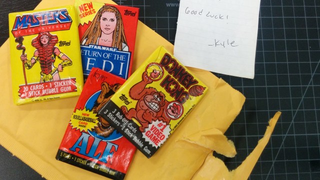
After I boasted about my willingness to try vintage gum, a reader sent over a care package with packs of 80s-era trading cards, gum intact. Here’s what happens when you try to chew bad gum that’s been sandwiched between wax paper and cardboard for 30 years. It’s not pretty. (Apologies for the focusing issue in the video. I was testing the video capabilities of the Sony A7 camera, and auto-focus switched on after we framed up and focused on the background. It’s artsy.)