


This week, Will and Norm are joined by Jeremy Williams to discuss World Maker Faire in New York, puffed cereal, LEGO artwork, the iPhone 5s, new Kindle Fires, the Surface 2, and GTA V. Enjoy!
The Talking Room: Adam Savage Interviews Tom Sachs

Tom Sachs is a New York-based sculptor, artist, and maker of wonderful things. His works include meticulously detailed foam core architecture and Space Program: 1:1 scale recreations NASA vehicles and equipment. Join Adam Savage for a conversation with Tom Sachs on the culture of making, contemporary art, Tom’s studio environment, and many other shared obsessions.
Show and Tell: Adam’s Favorite Video Game
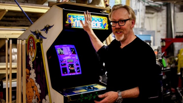
Adam doesn’t play many video games, but he does have an affinity for one particular one from his youth. For this week’s Show and Tell, Adam shares his love for the classic arcade game Millipede and gives a demo of the cabinet he has set up in his workshop!
Episode 185 – We’re Leaving On a Jet Plane – 9/19/2013

Adam’s Talk from Boing Boing: Ingenuity
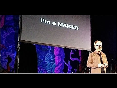
Adam talked about his ten ground rules for success at Boing Boing’s theatrical show in San Francisco last month. Definitely worth watching.
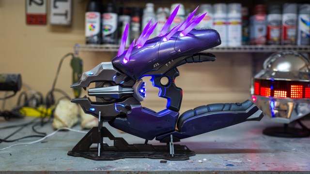
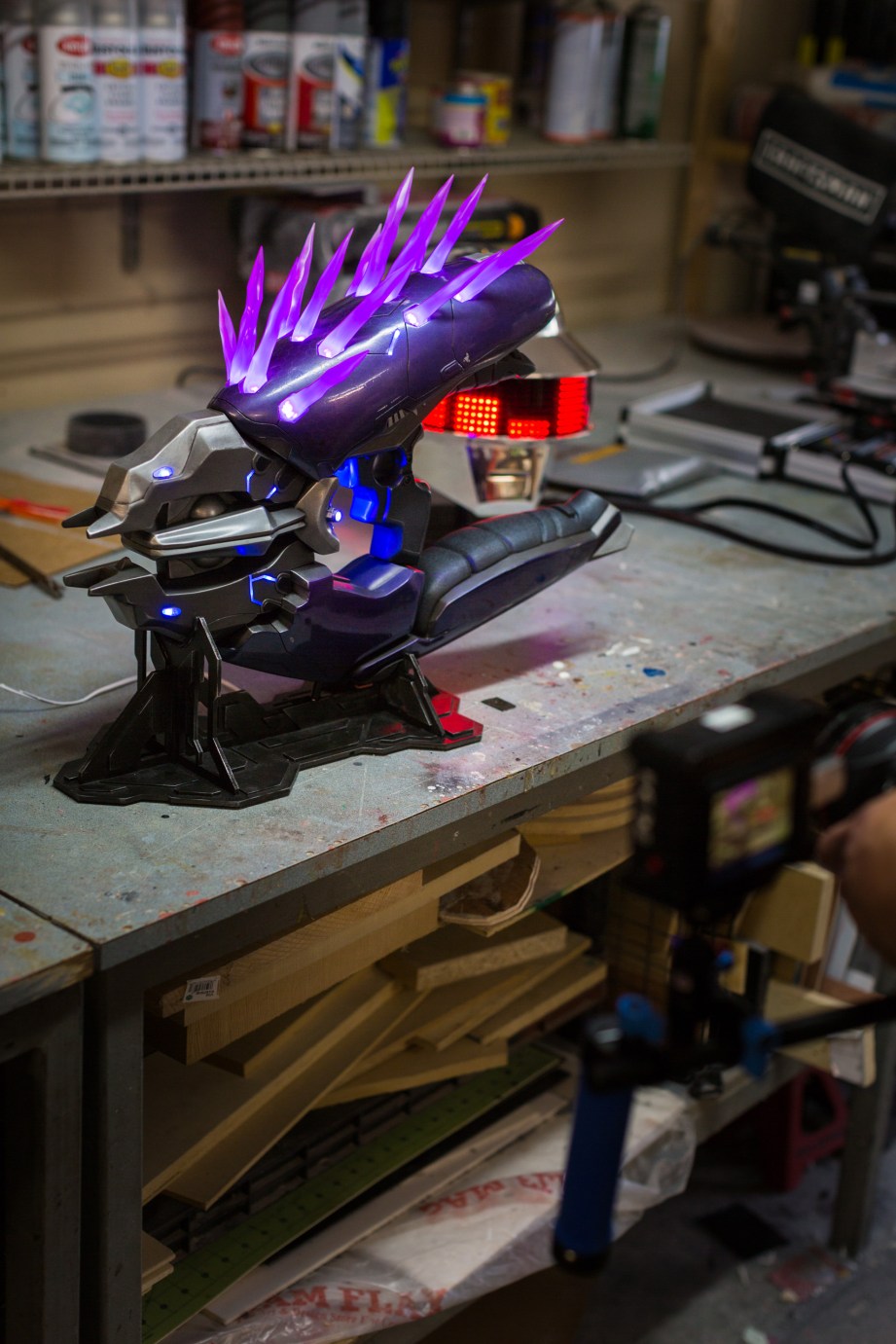
The Volpin Project: Building The Halo Needler
Norm here. Along with regular Tested readers, I’ve had the pleasure of following along with Harrison Krix’s build logs for the Halo Needler prop project that he’s been working on since the start of this year. This was a project that began when Harrison and I caught up for a Maker Profile interview late last October, and I tossed up the idea of a collaboration with Tested that would chronicle the journey of one of his props, from concept to completion. We had first met at Whiskey Media’s Big Live Live Show where Harrison flew to San Francisco for a segment about prop making, but I had been a fan since seeing photos of his Mass Effect M8 Avenger rifle prop back in 2010. Harrison’s prop making skill is renowned in the replica prop community, but just as impressive is his ability to write comprehensive (and comprehensible) build logs documenting his work.
Bringing a fictional video game object into reality is quite a feat, but pulling away the curtain and showing people how the magic is done is what makes Harrison a model maker.
That behind-the-scenes story is what we wanted to get across over the past year of The Volpin Project–both a sense of being along for the ride during the Needler’s birth into the world of the real, and a document of the build process though the lens of someone who quit his day job to make these props for a living. Through 15 check-ins with Harrison, we not only saw the Needler literally take shape, but got a crash course in some of the tools and techniques prop makers use–a starting point and invitation for anyone to dig deeper into those topics. If, at the culmination of this project, we left some of you both awed and inspired to make something of your own, mission accomplished.
This page commemorates, consolidates, and celebrates the Needler prop build, summarizing the key milestones from The Volpin Project series. I encourage you to read the entirety of the project build log if you’re interested in learning more about prop making, though if you’re just here for the pretty photos, that’s OK too! Harrison, take it away!

Introductions
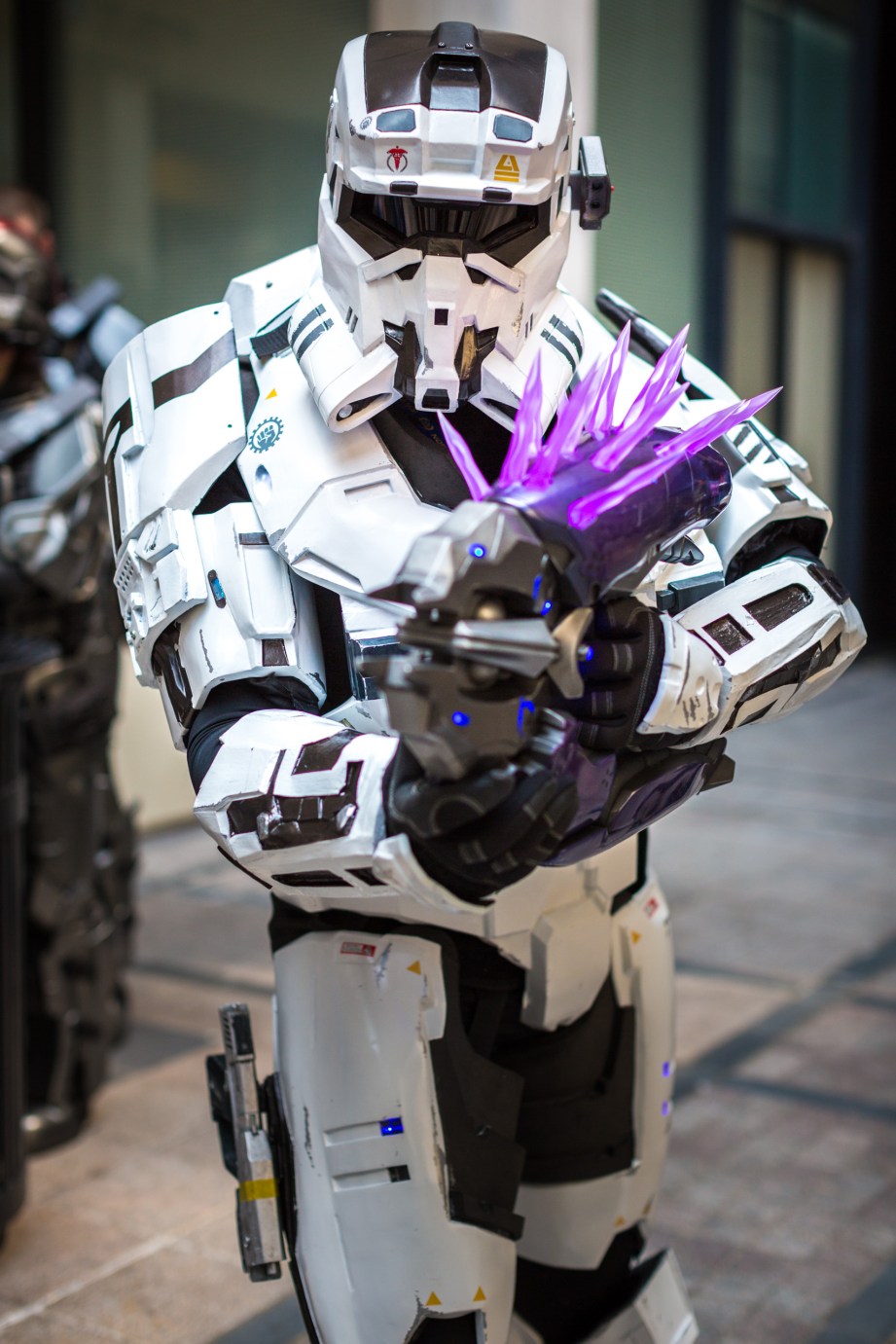
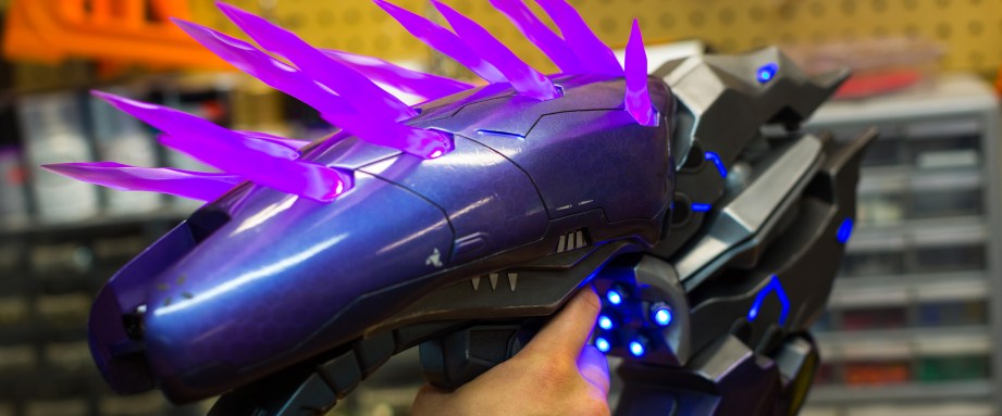
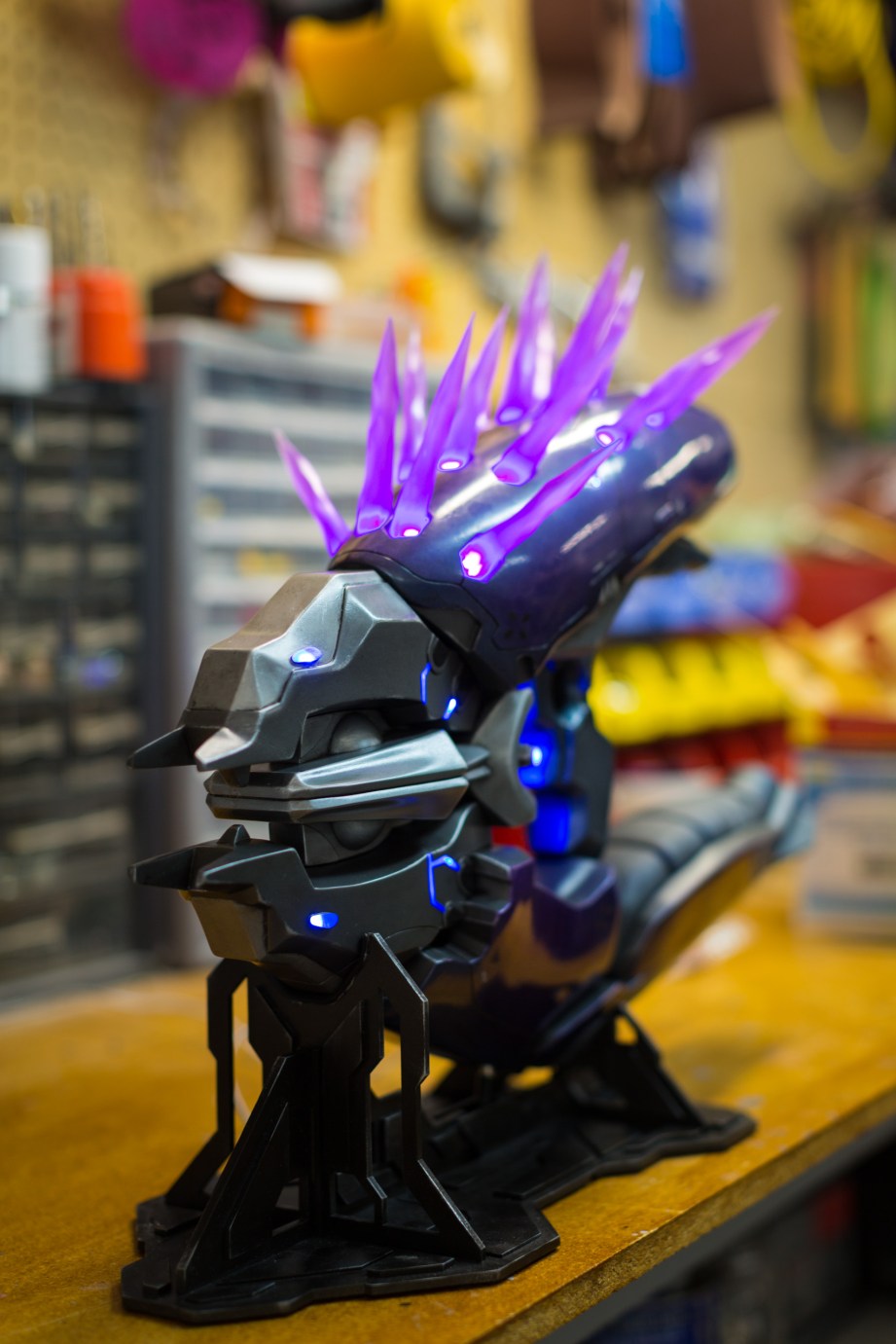
The Halo Needler has been on my personal list of stuff I really want to make since I first played Halo: Combat Evolved back in college. The design of this gun has undergone a lot of changes in the past 12 years and six Halo titles it has appeared in, but it’s always remained one of my favorites. The complexity of the finished prop rivals that of my Daft Punk helmet replicas, and I couldn’t be happier with the results.
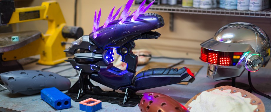
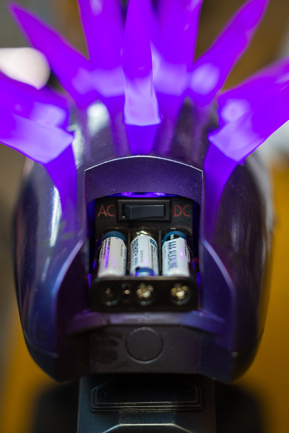
A summary of the build is really a listing of numbers: 15 different molds were created for the individual components and 24 cast parts go into the final product. There are 54 LEDs that illuminate the needles as well as various blue accents throughout the body of the gun. The final product is 31 inches long, weighs 10 pounds and can play three sound effects from Halo Reach: power on, semi-auto fire and full auto fire. Also built into the gun is the ability to run the electronics from a wall power adapter or three AAA batteries.
But it all starts with some game screenshots.
Design and Blueprinting
Good blueprints are, in my opinion, the key to a really successful prop. There’s an old saying that goes “garbage in; garbage out” which can refer to anything from the quality of materials to the planning of the project. In this case, a good set of blueprints will make sure that all your parts fit together properly and are accurately scaled to one another. It’s the foundation of the project, and just like an architect wouldn’t make a house without a detailed set of plans, a good builder should take the time to spend a while on solid blueprints.
These have to originate from somewhere, and if you happen to be into making props from video games like I am, then you’re in luck. If a game has come out on PC, there is a pretty good chance there’s a vibrant and thriving modding community out there for it. These are players and artists who have been able to extract the models and textures from the game and edit or manipulate it in order to create aesthetic or game-changing mechanics mods.
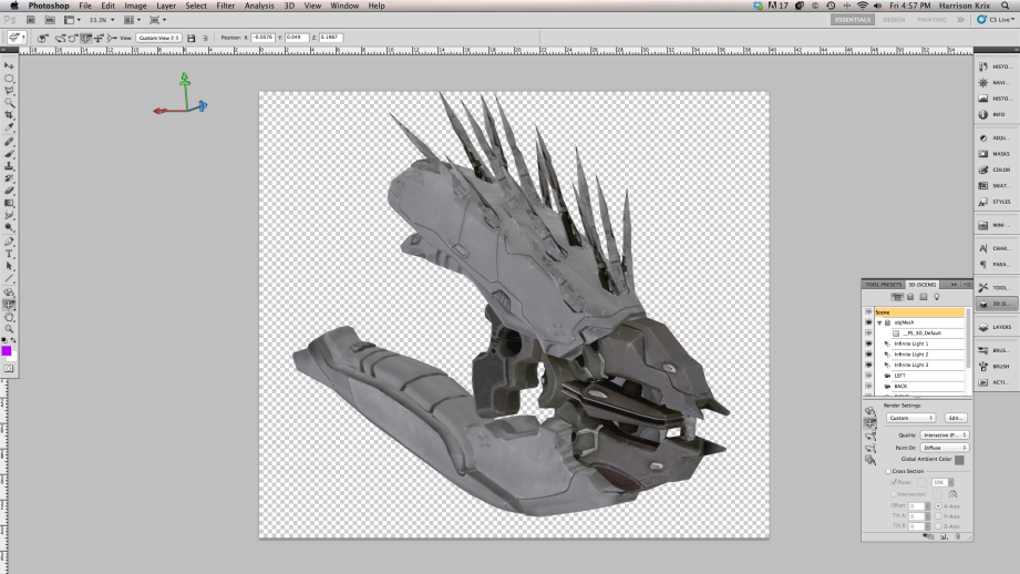
Some games, like Skyrim, even come with a handy built-in model viewer! Halo: Reach, as a console game, doesn’t, but I really lucked out and happened to get in touch with a modder who had pulled the Needler’s 3D files out of the game, which I was able to open in Photoshop as an .obj file and manipulate to my needs.
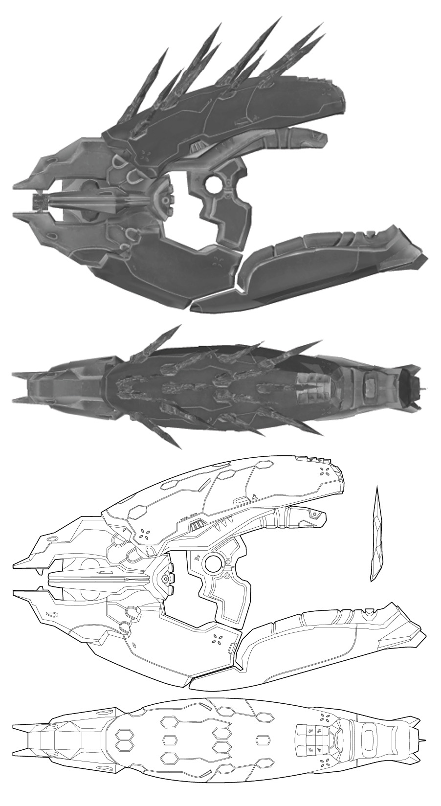
From these models files, I take screenshots from a multitude of angles: top, bottom, sides, front and back, etc. It might be that not every project needs this much detail, but the more you can put into your blueprints, the better. Its a good idea to grab 3/4 angle shots too, showing the piece from other perspectives than just these flat-on views. This will allow you to see how certain panels, lines and segments interact better than a flat angle shot would.
After I source enough screenshots, the individual references are tiled together in Adobe Illustrator. One benefit of vector-based blueprints is that you don’t lose any detail when scaling your piece. Scale is another very important element; props that are too big or too small will look incorrect no matter how well built they are. I really lucked out with the Needler, because Microsoft has given their community a whole wealth of information about the HALO universe, and I was able to extrapolate the Needler’s real-life length for scale.
Crafting a Prototype
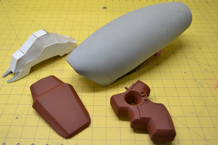
With the blueprints completed, the next step was just as crucial: planning how to build the actual prop and selecting the proper materials. The Needler itself is a combination of many different elements–organic curves as well as geometric edges–and different materials and techniques were suited to making its many components.
The Needler was actually built twice for the purposes of this project. I started off by making the various components as individual pieces, mostly solid, and comprised of various plastics, wood, clay, and resin. These parts, called “masters”, were then molded and later cast in urethane resin. This yields lighter parts composed of one type of material, making them stronger as well. These cast pieces are what make up the finished product. Additionally, castings can be made hollow, which makes running wiring for illumination and batteries much, much easier.
When making the master prop, it’s a good idea to consider the individual components of the piece as their own little projects. You’re not a renaissance sculptor carving your space gun out of a block of marble, and approaching a build in that way tends to get frustrating pretty quick. By breaking the project down into smaller components, you can concentrate on which piece requires what build technique without getting bogged down in making everything look perfect all at once.
I’ll admit I’m not a sculptor of any sort, but I’ve figured out many ways to skirt that shortcoming and use a bit of mechanical engineering and drafting tools to get pretty solid results.
My technique is a pretty simple concept, but it might not immediate jump out as a solution for those starting on their first project. Essentially, you build an object by assembling it from sheets of material (sometimes referred to as “slicing”) from the inside out. This process is convenient when making large objects with flat sides that have a lot of intricate geometry. Beveled edges can be created by using clay or Bondo to fill in the spaces between layers.
Since layering works best with large sheets, there are a lot of material options to choose from. One of the biggest go-to’s in DIY prop making is a cheap and readily available wood called MDF (medium density fiberboard). Think IKEA furniture backing. It is a great starter material that can be shaped with simple tools like a jigsaw and dremel. MDF can go a very long way in a project if you want it to!
A step up from MDF in many aspects is a material called “sintra” or “PVC foam board.” Sintra is a foamed plastic sheet that is lighter, easier to glue and sand, and can take a little bit more detail than MDF. Unlike MDF, it can be heated to take simple curves, making accent details much easier to accomplish. For more intricate details, I used plastics including acrylic and styrene. Both of these materials come in very thin sheets and can be laser cut, shaped with heat, and vacuumformed.

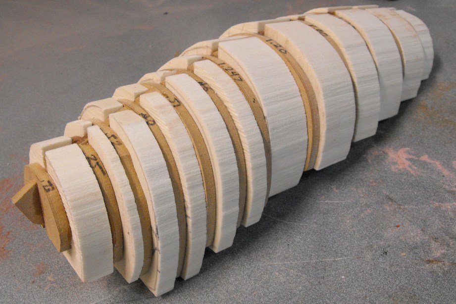
Domes and compound curves are a bit trickier than flat forms and geometric shapes. Many builders will scour hardware stores for similar shaped items and enlist them for parts, but I went something a little more exact. My preferred method is to use the flat views built in the Illustrator blueprints to create an internal framework that defines the outer edges of a curved shape from all three dimensions. What I end up with is a skeleton that can be filled with a variety of materials–foam, clay, resin, or wood–and sanded down into the proper curved form. A little bit of artistic interpretation may be necessary to get the curved forms just right, and some extensive sanding and Bondo work may be necessary. But the frame gives me a definite stopping point, which will go a long way towards getting the curves precise and to scale.
For smaller detailed shapes, I like to use a material called “Apoxie Sculpt” made by Aves. Apoxie is great for sculptors who, like me, kind of suck at sculpting. It’s even better for people who know what they’re doing, but the beauty of this material is how well it sands and smooths out. Apoxie can be drilled, tapped and machined and is incredibly dense and strong. It’s also quite heavy, but again this doesn’t matter with the master parts.
Moldmaking and Casting
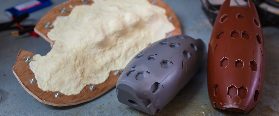
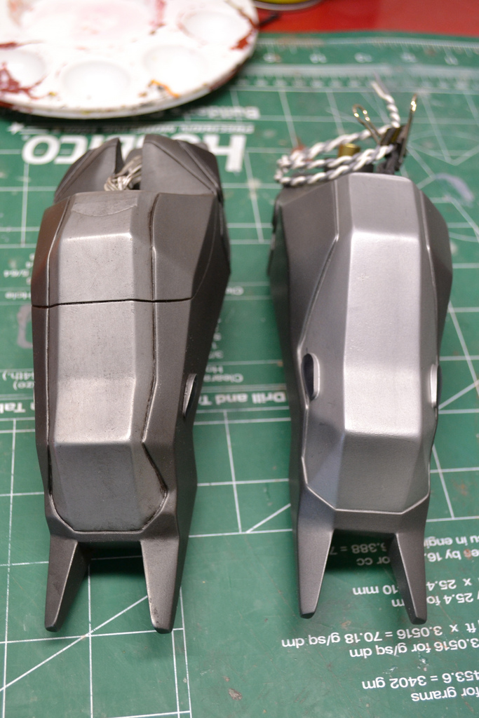
At this point, our Halo Needler prop prototype was somewhere around 15 pounds, an amalgamation of wood, foam, Bondo and various types of plastic. While the shape of the whole thing was spot-on, the prop left a little bit to be desired with how heavy and fragile the mish-mash of materials ended up being. The parts here had to be molded, then cast in urethane plastic. This then yielded a piece that is both far lighter as well as more durable than the prototype, since it’s all be one cohesive material through and through.
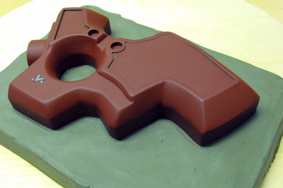
There are many types of techniques to make molds, and just as many types of materials to make molds with–the process I used here was for making hard copies cast in rigid plastic.
The part to be molded is referred to as a “master” or sometimes as the “sculpt.” For example the grip of the Needler prototype is made from MDF, Acrylic, PVC, Bondo and some epoxy clay. This is the grip master.
To make the mold, the material I’m used was silicone. The “mold” is anything into which casting material is poured in order to make a copy. Many people confuse the word “mold” with the finished result of the casting process. The pieces that come out of a mold are referred to as “castings.” Molds can be made from plaster, resin, silicone, latex–any number of materials based on the end goal of the mold and the part that is being replicated. I used silicone because it is versatile, lasts through many uses, and yields the best results for the type of work I do.
There are two kinds of silicone you’ll run into when making molds: “Platinum cure” and “Tin cure“. Generally tin-cure silicones are cheaper and less prone to curing issues, but less durable and can also shrink over time. Platinum-cure silicones shrink less, are very durable and more archival, but are more expensive and can be finicky about curing depending on environmental factors as well as what kind of materials the mold master has been made from.
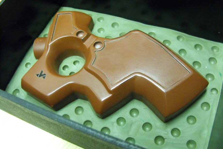
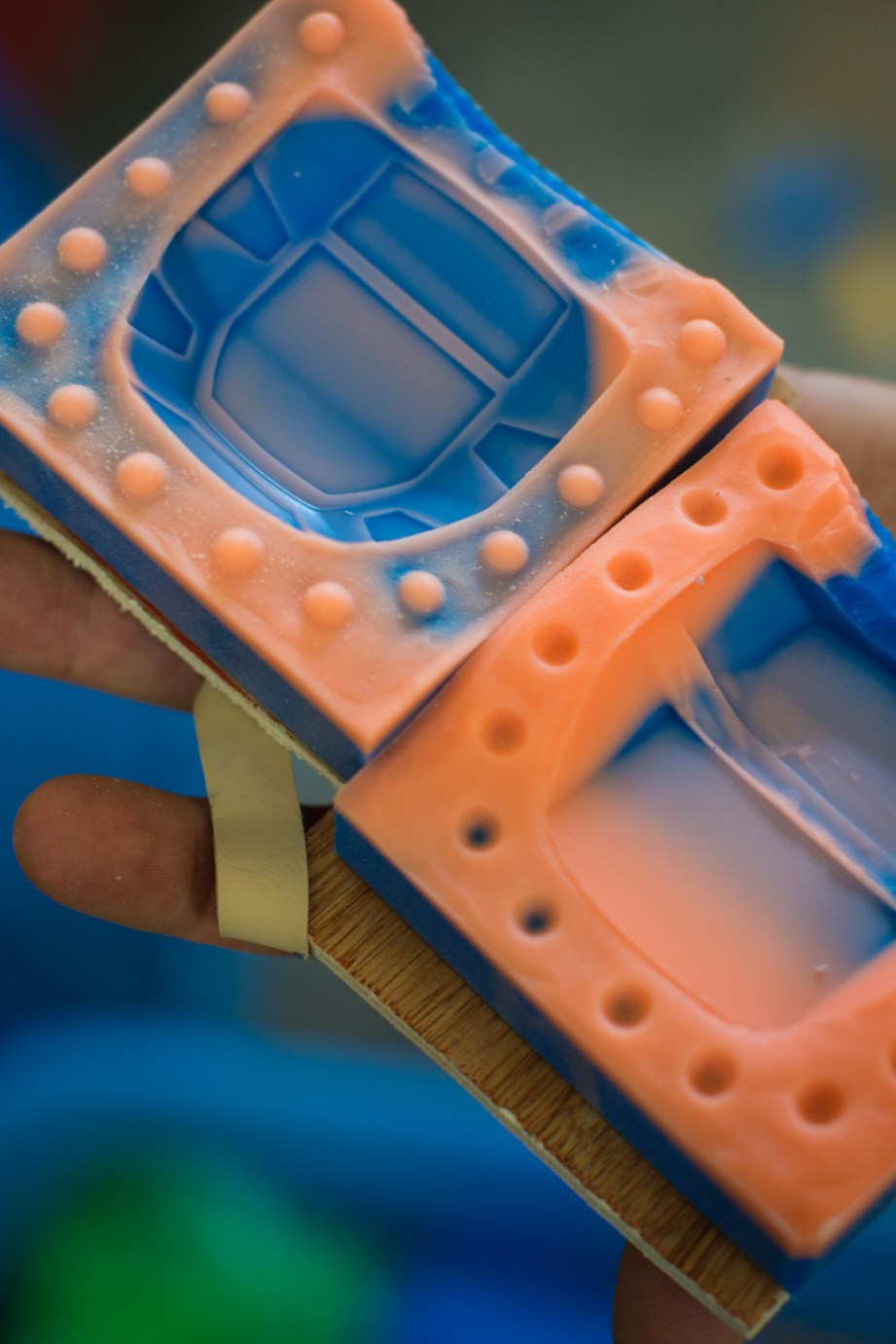
The easiest kind of mold to make is a one piece block mold. This is useful for making parts that have a flat back and detail on only one facing side. And if you have a component that has detail on both sides, you can make a two piece block mold, like what you see on the right.
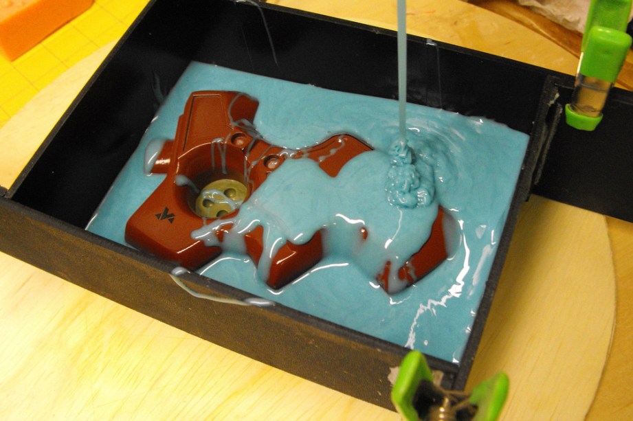
As a simple example of making a one piece mold, a piece of the Needler was placed into a mold box with a flat base. Clay was used to seal the mold box to prevent leaks around the base and edges, and silicone was mixed and then poured over top of the master part. After allowing six hours of cure time (for this particular silicone) the walls were removed, then the master part was demolded from the silicone.
Other parts of the Needler were replicated with more complex molding techniques, such as brush-on moldmaking. The basic premise here is gradually building up layers of silicone onto a part until the desired mold thickness is achieved, and then wrapping that floppy mold in a rigid mold jacket (or mold mother). Once the molds were finished, I was then ready to make copies!
Casting techniques and materials will vary depending on the final use of the piece, but for the purposes of this build I focused on urethane casting resin and leaving out other plastics such as epoxy or polyester. In my detailed build log, I covered the process of casting solid components, hollow parts, and even translucent pieces as well.
Embedding Electronics
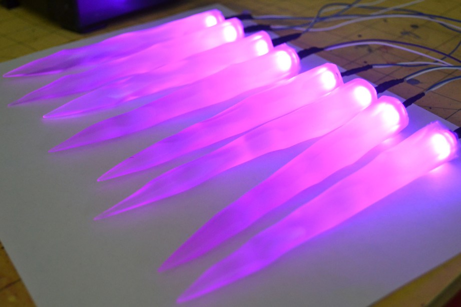
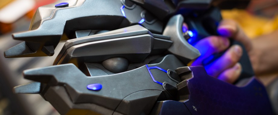
Static props are fine if you’re making a sword or a shield, but when it comes to a space combat theme, everything has to have LEDs in it. The Needler ended up having 54. Sound can also lend a bit of fun to a replica, and while it’s always going to be difficult to match the on-screen experience that a surround sound system gives you, it’s still fun to pull the trigger and not have to make the “pew pew” effect yourself.
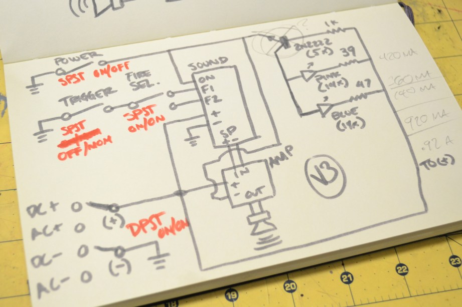
For the Needler, I started out by making a list of the things I wanted it to do and where/how it needed to do them. Lights had to come on via a switch, and I wanted a “start up” noise to accompany this effect. I also wanted a push button trigger that would toggle between automatic and semi-automatic fire. From my experience with audio in props before, I also knew I’d need a small amplifier to bump up the volume. All of that was a bit much to organize in my head so I drew out a few schematics.
There are a myriad of switches available to hobbyists and a lot of fun tricks you can pull off when you start feeding them into one another. For example, I needed one button to control both semi and automatic firing noises, but the sound chip I decided to use can’t be programmed to swap effects. To get around this, I wired the trigger switch output into a second toggle switch that selects either the automatic or single firing sound effect. The trigger itself is a momentary push button that glows blue, because why not?
Authentic Needler sound effects were sourced from The History of Halo and edited together into one audio file. I ordered a pre-programmed sound module from replicaprops.com, and bought a small amp from Sparkfun. This little mono amplifier made all the difference in the world when it came to the sound effects. I’ve put audio electronics in props before but the speakers have been run directly off the sound chip. For something like a static display ship model where you only want a gentile engine hum this would be fine, but adding an amplifier to the circuit gives the Needler firing noises some much needed oomph.
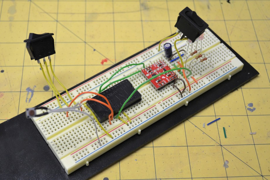
A handy piece to have around when you’re mocking up your circuit is a breadboard. I used one to mock up the audio and illumination circuit first here to make sure that everything was working as planned and there weren’t any faults in the circuit diagram I originally drew.
For illumination, I got my LEDs from superbrightleds.com. LEDs need resistors to properly limit the voltage they receive so they illuminate properly without being damaged. There’s an equation for this, but there’s also a handy website! With a few values for your bulbs and power supply, you’ll have the proper resistors sorted out in no time by going to ledcalc.com.
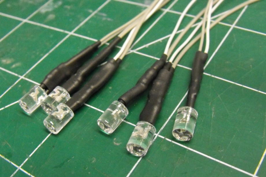
Embedding the LEDs into the needles was no problem. Each pink LED was individually wired and I drilled a 5mm hole into the back side of each needle. When it came time to mount these into the body of the gun, I just cut off the base at an angle, leaving the straight hole intact to make sure the light shines the correct direction.
The last thing I’ll mention is a bit of a luxury, but when it comes time to install all of these components into a finished prop I prefer to have things on a custom printed circuit board. While it is possible to solder chips and leads onto a piece of generic perforated circuit board and jumper all the connections, custom PCB printing has recently become inexpensive enough for hobbyists to employ even with strict budget projects, provided you don’t mind a couple weeks for production time. I designed these boards in CadSoft’s EAGLE board layout editor, and while that is a very powerful program (even the free version!) it does have a somewhat steep learning curve. My board design was then sent off to oshpark.com for printing.
The Needler is powered by either an AC connection or on-board battery power. I devised a removable battery cover for the rear of the Needler using, but what else, magnets!
Painting and Weathering
Before painting to commence, I had to prep the Needler components by figuring out their mounting points. It’s important to have a plan for assembly of a prop before putting a shiny nice coat of paint on it, because it would be difficult to keep from marring a fancy paint job with all the drilling and cutting that needs to be done. When the individual parts of a project are still raw resin, you can afford to have a scrape here and there figuring out the best way for everything to fit together. Once things are painted, the last thing you want to do is fret over every bit of dust that might damage all your hard work.
Many people might choose to glue their props together, and a lot of my earlier pieces were held together mostly with superglue or epoxy. My preferred method now is to have as many pieces held together mechanically (read: screwed together) as possible. This may be reinforced with a glue joint as well during final assembly, but securing pieces together with bolts and screws ensures that every part goes together the same way each time it’s put together.
With all the holes cut, drilled, tapped and countersunk, it was time to start prepping things for primer and paint. In preparation for primer, each part needed to be given a slight scuff to enable the paint to stick adequately. It isn’t necessary to go over the entire thing with sandpaper, and doing so might actually blunt some of your sharper details in the casting. The goal here was to knock any sort of shine off and have a piece with a uniform dullness to it that shows the surface has a slight roughness to it.
After more hours of sanding, priming, filling, sculpting, molding casting, cutting and drilling than I care to count, it was finally time to get some color onto the Needler. Some parts of the Needler were very easy to paint and only required the application of a single color. The grip, rear vents, lower handle attachment, and “barrel” (for lack of a better term) are mostly single color with a few accents here and there. The base coat of paint was done with Testor’s Buffable Metalizer lacquer, in magnesium (the lighter silver) and gunmetal (the darker). Accents and highlights to these parts were applied later on with brush paints.
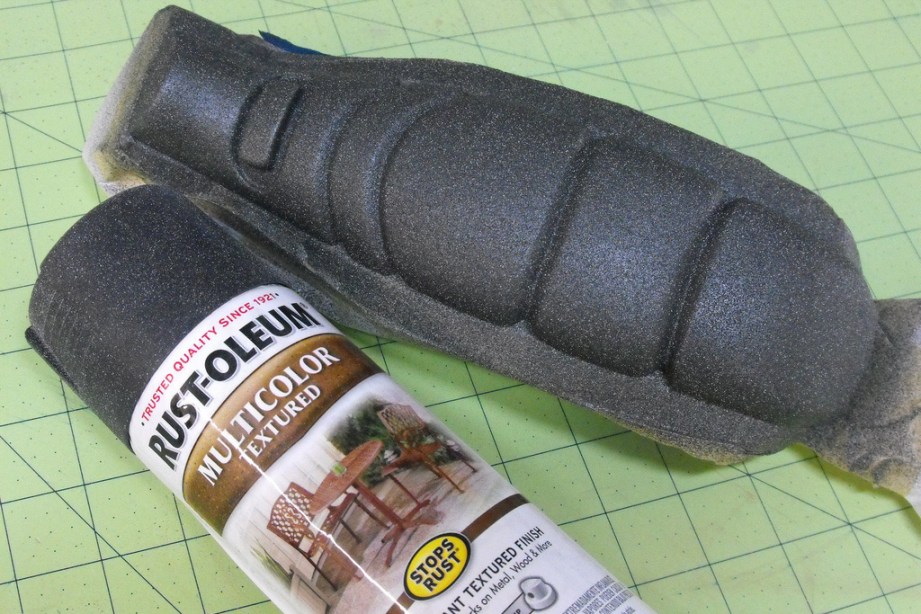
The lower casing on the Needler has a padded-looking grip with a dark blue pebbled texture covering its surface, so I used Rustoleum “Multicolored Textured” spraypaint.
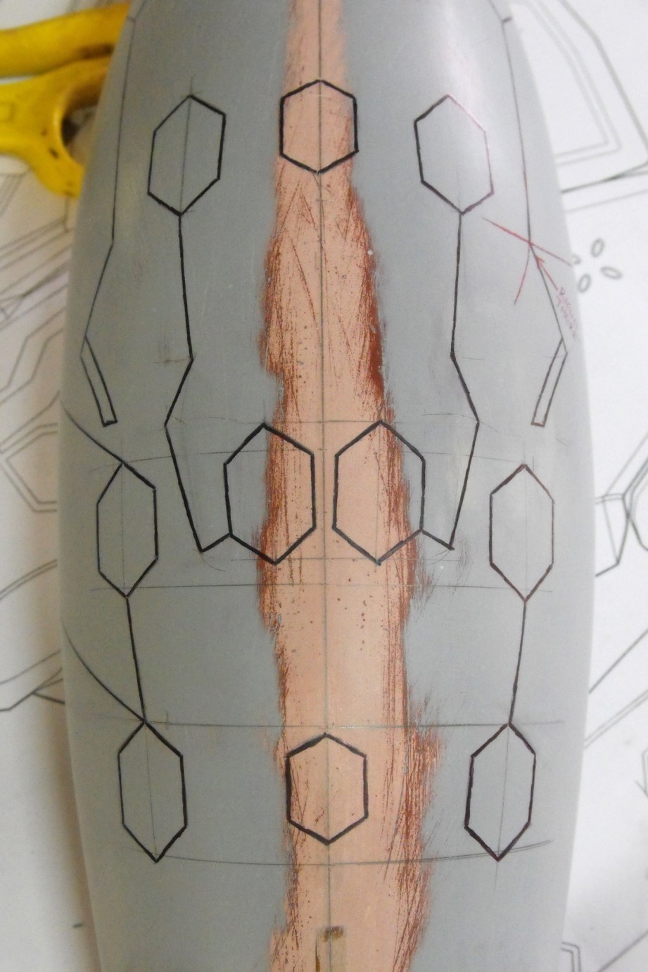
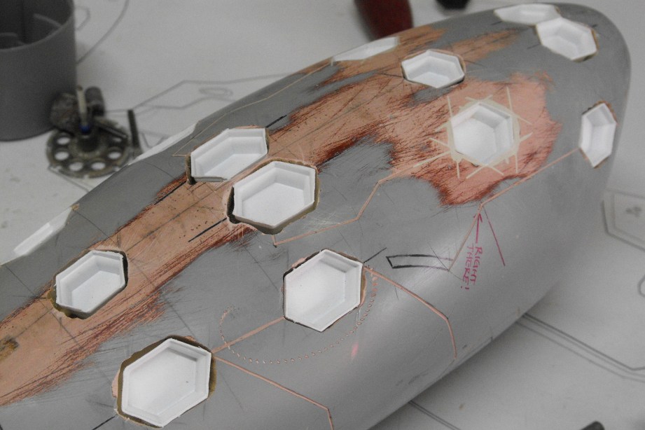
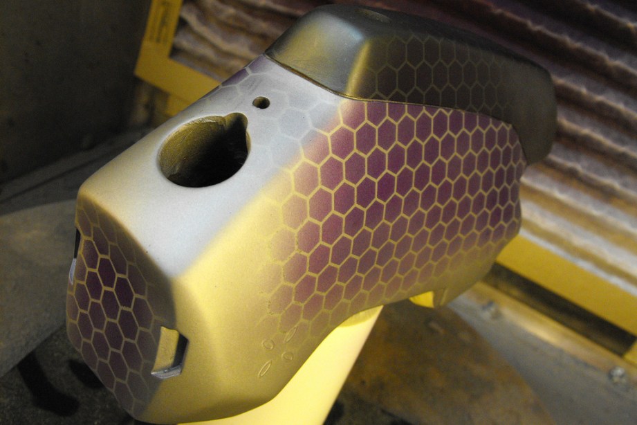
That iconic purple outer shell was a little trickier. The technique I settled on for creating the subtle hexagon pattern on the surface of the purple parts required a lot of thin passes of translucent paint to get a color-shift effect, and I found the best way to do this was over a coat of bright silver. After the two base coats had fully cured, I set up my laser cutter to trim out a large hexagon paint mask out of stencil vinyl.
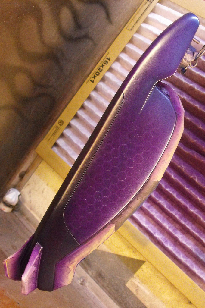
Since the large surface area and compound curve of the purple sections meant getting the pattern to cover the entire surface seamlessly would be nigh impossible, the pattern was simulated by cutting various shapes of hexagon mask and applying them across the surface of the gun in the same facing direction
When these areas were painted, I feathered out the purple color at the edges of the paint masks so the seams wouldn’t be apparent. The purple used here was an enamel pearlescent clearcoat. When the rest of the part is painted with the purple clear, the areas of the casings without hex patterns blend into one another, while the masked off areas appear darker, leaving the negative space brighter due to the silver basecoat. I also used a little bit of a metallic dark blue, thinned out with some enamel clearcoat, to give the purple a bit of a color shift around the sharper edges and corners. This isn’t true “color shifting” paint, but the gradient of purple and blue across the surface does mimic the effect pretty well. And once these parts set for two days, I treated them with four coats of enamel clear–thin passes, five minutes between each coat.
After all the prop parts were basecoated, shiny and new, they needed a little bit of faux history infused into them to complete the transformation from plastic to replica. One part storytelling and one part fakery, this is the process known as weathering.
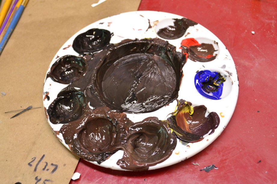
Back when I first started making props, the weathering process mostly involved smearing black and brown paint over the surface of something. While I still do that, there are a few steps and refinements I’ve learned along the way which have made my final paintjobs more realistic. This includes using a mix of colors besides brown and black to create the look of dirt and grime, and the judicious use of wet paper towels to create random textures. I go in-depth into each weathering technique here.
Halo takes place over a variety of environments, but for this prop I wanted the Needler to look like it had lived aboard a ship for the greater part of its life, then been deployed to one of the more forested areas of the ring. The brown areas should be dark to imitate mud or fine rich soil that had been cleaned away over time. When weathering a piece, consider where grime and gunk will build up over time. Most typically, in the creases and recessed areas.
Once the base weathering was complete, the final step (and my personal favorite) was drybrushing. Drybrushing in this case was the process of using silver paint on higher edges of a prop to simulate scuffed paint and the metal areas beneath. This is another process where you’ll need to consider the life and utility of the item you’re creating; a pistol would have a lot of scuffs around the trigger, trigger guard, magazine well, safety, ejection port, etc. Areas that would be handled often or would be in danger of contacting an abrasive surface when the weapon is set down should show signs of wear and tear.
Weathering should continue after you’ve assembled your prop. Intersections between components will need another pass of dirt and grime, and you might notice certain protrusions that need a bit of drybrushing as well.

A Project Completed
It’s a very fortunate artist who gets to select the works they are commissioned to build, and I can’t thank the Tested guys enough for sponsoring this project. The Needler is something I’ve wanted to bring out into the real world for a very long time now, and I hope the articles from the project help you to bring your own creation to life as well.
Photography by Norman Chan and Harrison Krix
How To Pick a Basic Lock

At its essence, a lock is puzzle. While its answer may vary slightly, the route to puzzle-solving success has remained largely unchanged since the pin-tumbler lock’s invention 4000 years ago in ancient Egypt. Manipulate the pieces in just the right way and the lock will yield.
Sure, a key is the easiest way in, but it’s not the only one. Eric Michaud, the co-founder of Toool.us, the US chapter of the Open Organization of Lockpickers, which promotes greater public understanding how locks work and when they might not, walked us through the art of solving the lock’s puzzle without a key.
What You Need
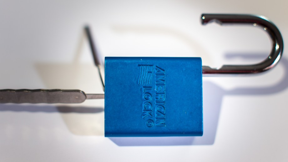
Lock: Any cheap, key-operated lock from the hardware store will do.
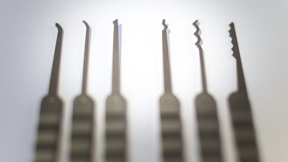
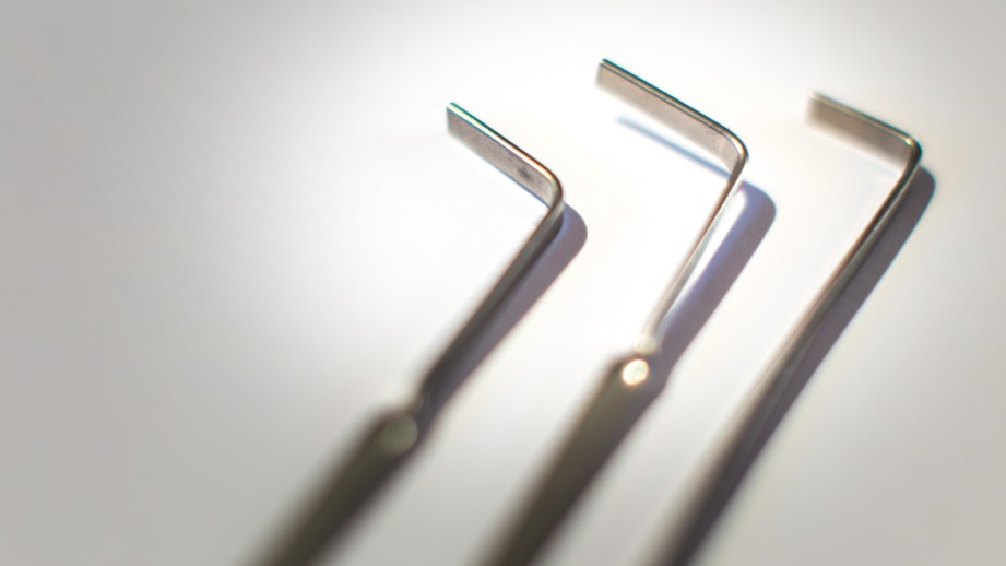
Tools: The basic path to success requires two instruments: a pick and a torque tool. Your basic pick will be a thin, pencil-length piece of metal that curves slightly upward at the end. The torque tool will be a flat piece of metal with the small end bent 90 degrees.
Understand the Puzzle
Before you can pick your way to the answer, you need to understand the puzzle and its pieces.
The two largest parts of a pin-tumbler lock are the body and the plug. They’re also the elements of the lock that you can see. The body is the container, and the plug, which spans the length of the lock, is the cylindrical part that rotates when you turn the key.
If a lock were nothing but a body and a plug, any old key would open the lock. But that wouldn’t make for a very secure system, would it? So lock makers decided to throw a perpendicular wrench in that turning mechanism by exploiting the intersection between the plug and the lock’s body.
The metaphorical wrench is actually a line of stacked pins, each broken at different positions. When the correct key is inserted into the keyway, its grooves and peaks will push up the pins into a pattern that will allow the plug to rotate freely.
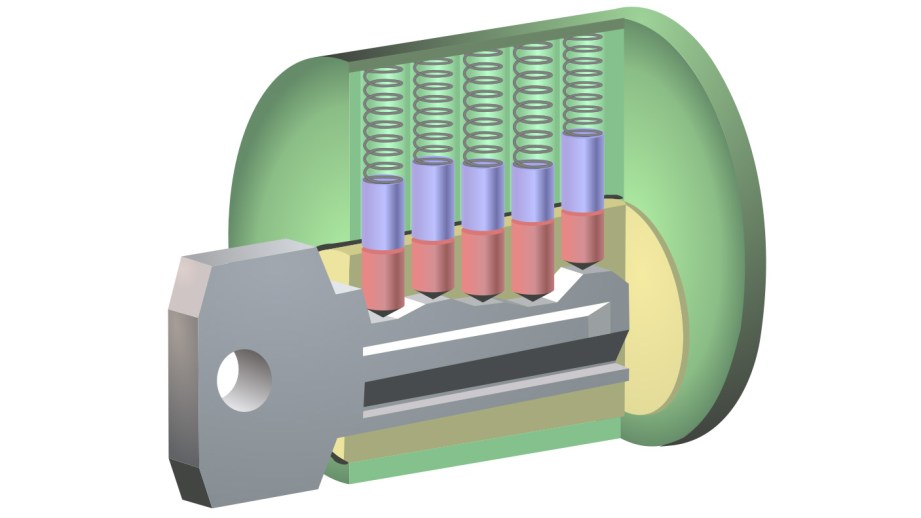
To understand how the pins work, imagine two erasers, like the ones on the end of a pencil, stacked on top of each other. One eraser hangs into the keyway like an icicle, its top flush with the plug’s outside edge. The other is stacked on top of the first, reaching up into the lock’s body. Where they touch is also where the plug and the lock’s body meet. If the erasers are aligned so they meet just at the shear line, the plug will rotate freely. But push the pair too far down into the lock, and the top eraser will straddle the two main structures, blocking the plug from turning and the lock from opening.
Why You Can Pick a Lock
Lining the pins up in a perfect row, as it turns out, is a bit of a manufacturing challenge. “The problem is that the drill bit will wobble so you get aberrations,” explains Michaud. “You’d think that when you apply pressure, all the pins would hit at the same time, but they don’t.” Only one or maybe two pins at a time will take the brunt of the pressure.
If you don’t know how many pieces are in the puzzle, it’s hard to solve it effectively. To count the number of pins, insert the long end of the torque tool all the way into the lock and push up. As you slide the torque tool toward you slowly, the pins will spring free with a click. Count the clicks and you’ll know how many pins you need to manipulate to open the lock.
Step 1: Get a Grip
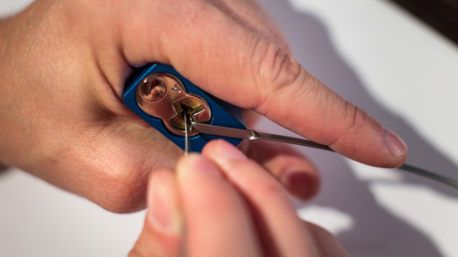
Hold up your left hand like you’re about to high-five someone. (Switch that if you’re a lefty). Nestle the lock upside down between your thumb and forefinger so the key hole is facing you and the lock’s bottom is flush with the back of your hand. Now rotate your hand down, fingers pointing toward you instead of toward the sky. The keyway should flip 180 degrees.
Step 2: Give It Torque
Insert the short end of the torque tool into the keyway and get it situated as low as possible. (You want to give yourself space to use the pick). The long end of the torque tool should extend toward your pointer finger. Rest your index finger on the long end of the tool, applying a slight amount of constant pressure. Michaud recommends just a few ounces, like that of a key-stroke. “If your finger is changing color, you’re pressing too hard,” says Michaud.
(Note on ergonomics: Locks can get heavy. Rookies will rest the weight of the lock on their wrists, but pros will advise otherwise. Either place your hand on your lap or on the cushion of the pinky side of your hand to ease the stress on your tendons.)
Step 3: Tease the Pins
Wiggling a paper clip around may work on the television, but be warned: it’s a small screen lie.
Instead, hold the pick like you’d hold a chopstick or pencil with the curved end swooping upwards. Insert the curved end as low inside the lock as possible. Remember how many pins you counted inside the lock? Well you can’t see them lined up in there, but you’re going to start testing them. Pin by pin, work your way down the line, cupping each pin with the tip of the pick and lifting gently. You don’t need to slam it to the ceiling; you just need to raise the stack to break at the sheer line.
If a pin is springy, skip it. The lock-picker’s target is the binding pin. You’ll know you’re prodding the right one when the pin gives back a little resistance when you try to lift it.
That tension means that your torque tool, which is trying to spin the plug, is pressing the pin against the side of the lock. Lift the bottom pin up just enough and its accompanying top pin, called a driver pin, will break ever so slightly over the sheer line.
The lock will celebrate your small victory by shifting ever so slightly toward your torque tool.
Continue to move back and forth down the line, testing the pins for stiffness and spring. When each stiff pin’s accompanying driver pin has cleared the sheer line—voila!—the lock should pop open.
Tools down! Now use that hand positioned for high-fives to actually give one.
Episode 184 – This Year’s iPhones – 9/12/2013

On this week’s episode, Will, Norm, and Gary discuss the new iPhones, iOS 7, the Vita TV, Intel’s latest processor, and the politics of solar panels and electric cars. All that, plus the latest books Gary and Will are reading, and the announcement of OCTOBERKAST 2013! Enjoy!
Transforming Adam Savage Into Jack Sparrow, Step-By-Step


Adam Savage Incognito as Jack Sparrow at Dragon*Con 2013

Dragon*Con is known for its cosplay, so Adam took the opportunity to blend in by putting on a meticulously assembled Jack Sparrow costume and, in an Incognito first, didn’t hide his face. Face Off’s Frank Ippolito once again comes to assist with transforming Adam into character, and it turns out that this is a makeup job that Frank has a history with! See step-by-step photos of the makeup process, with Frank’s commentary, here!