


As they prepare to leave for PAX Prime in Seattle, Will and Norm discuss the Napa earthquake, Amazon buying Twitch, living inside a hologram, and the biggest Kickstarter ever. All that, plus our PAX plans, what we’re testing, and your questions answered. Enjoy!
Adam Savage’s Incredible Muscle Suit
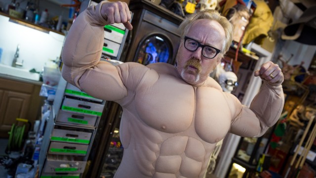
Adam invites us to the Cave to check out a new costume that he can’t wait to try on. Without knowing what it looks like beforehand, we get to see it for the first time and are left dumbfounded. It’s one of those things you just have to see to believe!
Bits to Atoms: Building the Millenbaugh Motivator, Part 4

Your patience has paid off–it’s time for the final print of the Millenbaugh Motivator! All the measurements have been made, a rough version has been completed, the final version has been modeled and prototypes printed. After three months of work, it was time to get this delivered to Adam. And that meant making a flight back out to San Francisco.
For my previous prints, such as the Octopod and Jetcar builds, I’ve used the trusty Objet Connex500. It’s a high-end polyjet printer that can print in various materials–even rubber. But as much as I like this machine, I also had access to a 3D Systems ProJet 7000 HD which could print at even higher resolutions and in stronger material, all of which would be especially useful for the Motivator. The ProJet is a SLA (stereolithography) machine that prints by ‘drawing’ the part in a vat of liquid resin using a laser that solidifies the UV sensitive material. Once a layer is finished, the print platform sinks further down in the resin, a fresh layer of resin is distributed over the top and the laser draws the next layer. The resolution can be set incredibly high, and I was told the parts would be dimensionally accurate, meaning a hole modeled at 3mm in diameter would print at exactly 3mm.
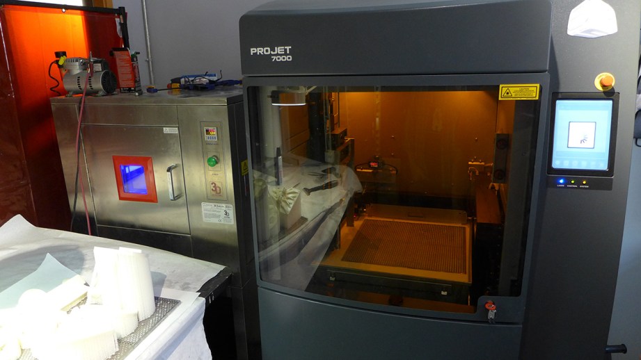
I was a bit skeptical of this claim, since typically you need to factor in some tolerances when modeling to accommodate the accuracy of the printer and behavior of the material. This has caused me frustration when 3D printing since a model built with tolerances for one printer won’t always print well on a different printer. I have done various versions of the same model with slight tweaks for different printers–an annoying and time-consuming task.
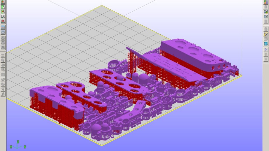
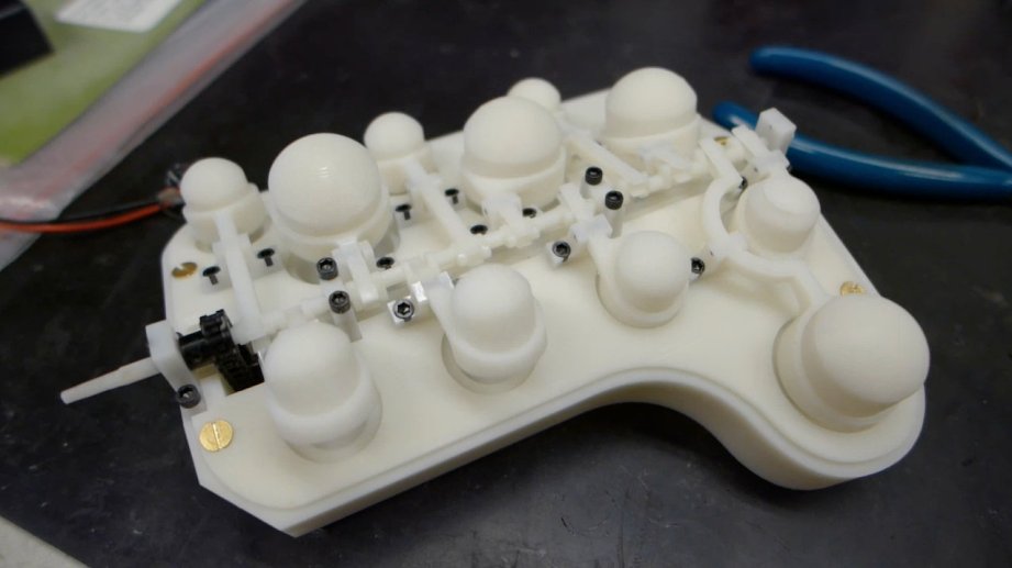
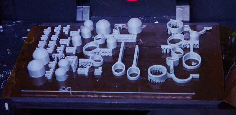
The plan was to do a test print of the Motivator, make any needed tweaks, and then print three final versions: one for Adam’s Mecha-Hand, one for Guillermo del Toro’s, and one as a back-up. This would be the first time I was able to print the crankshaft so I was anxious to get the test print. All the parts were laid out in the print software, oriented and supports were automatically generated. The ProJet uses a lattice-like support structure for each part since they can’t be floating around loose in the resin tank. The support is very fine and easy to remove but it helps to orient parts with hidden surfaces facing down toward the print bed. This way, visible surfaces will be as smooth as possible.
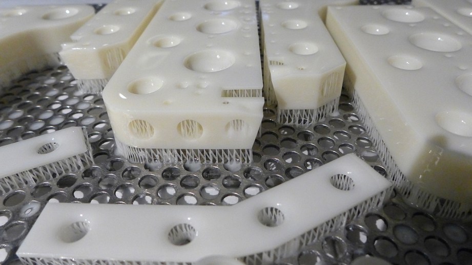
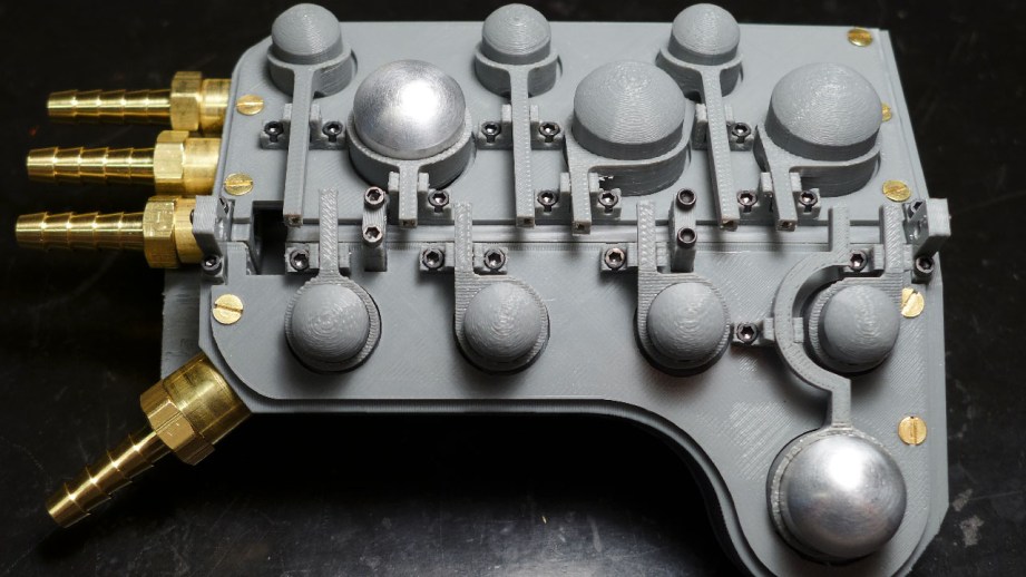
One complete block with a few extra parts took about 12 hours to print.
One complete Motivator with a few extra parts took about 12 hours to print. When the parts come out of the printer they’re covered in liquid resin from the tank and must be washed in alcohol. After cleaning they are ‘baked’ in an UV ‘oven’ for a few minutes to ensure the resin is completely set. Even after that, I found the parts were slightly tacky and needed to be hand scrubbed with some more alcohol and they still took a few more days until they were tack-free. The parts were gorgeous, the nicest 3D prints I have ever done, and they were indeed dimensionally accurate as every piece of hardware fit perfectly. The crankshaft even looked great but it had a good bit of flex to it due to the print material.
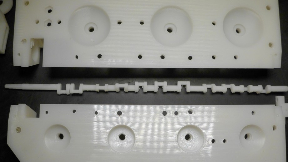
The test parts assembled exactly as planned and the crankshaft fit with only minor clean-up needed. There was no way that I was going to build the test Motivator and immediately fire up the motor, so I had made a handcrank that would slip on the end of the crankshaft to test it manually. I gently rocked the handle back and forth and the Motivator made a bunch of terrible squeaks and refused to budge. There was too much ‘gription’ between all the plastic parts but a drop of light oil on each crank pin made everything work! The crankshaft did flex a bit but I think that actually helped more than hindered. I installed the motor, adjusted the chain tension and ran the Motivator under power at a moderate speed successfully, so I shot a quick video and sent it off to Adam–he was pleased!
Manual crank test of Motivator for Adam.
With the success of the fully functional test print, it was time to print the final three to take to San Francisco. The test print turned out so well that I only made a few slight tweaks for the final print. I also decided to laser cut the top plates to save some time and money and it was easy to do since I had modeled the plates using splines. Laser cutters typically use 2D line drawings as the cutting file, so the splines translated perfectly. Since I had used standard material thicknesses when modeling, I was able to easily cut the plates from ABS sheets at a fraction of the cost of 3D printing.
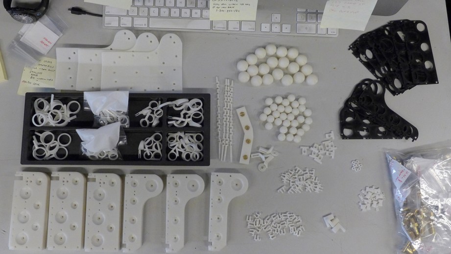
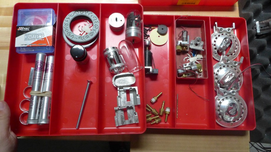
Originally, Adam wanted me to build one motivator and bring the parts for the other two but the prints were finished so close to the deadline that I wasn’t able to put one together. All the parts got a final alcohol scrub, sorted and packed in my carry-on bag (there was no way I was trusting these in checked luggage). I had a bag bulging with weird parts, in addition to my Curta calculator and Nagra spy recorder–it looked like a crazy person’s bag on X-ray, but they just waved me through at the airport. My wife and I spent two great days at Adam’s shop and I was able to fully enjoy the experience this time. As you all know, it’s a wonderland for people such as us and I took a ton of photos and tried on a bunch of his stuff. As a super-awesome bonus, that was the same weekend that Marty Cooper did his augmented-reality animation in the shop. Marty was very nice and fun to watch at work.
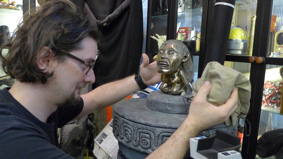
Adam and I sat down and went through all of the parts. He was really happy with the quality and immediately started testing the finish of Rub n’ Buff on a few pieces. He was happy enough with the 3D printed valve domes that he ended up using them instead of the cigar tubes–I’m sure they’ll find their way into another project. We shot our video discussing the Motivator and Adam put it through its paces. I had been running the motor at 3.7 volts and Adam cranked it to 12. I was convinced it was going to fly apart or start smoking, but it made it through in one piece. He showed me all the loose parts used for the Mecha-Hand and even offered me some extras. I was so tempted, but I know that I will never build the entire prop myself, so I told him to offer them up to those on The RPF who are actually building Mecha-Hands.
My wife Kate and I also got to spend quality time at the Tested office where Norm and I shot Show and Tell videos for the previously mentioned Curta & Nagra. Norm was a great host–Kate and I had the honor of experiencing the highly disappointing Comic-Con exhibit with Norm and his girlfriend at the Oakland Museum of California, although they made up for it with a great Giant Robot exhibit. Since Adam and I didn’t get the chance, I built an entire Motivator on-camera for Tested Premium Subscribers. Our five days in San Francisco were absolutely fantastic and a nice wrap-up to three months of work!
A week or so later, Adam had some bummer news: after painting and assembling everything he was unable to overcome the additional friction the paint added and the Motivator wouldn’t run. Luckily, that same week, online 3D printing service Shapeways had changed some of their restrictions for printing metal and I was able to finally place an order for a 3D printed bronzed steel crankshaft. I had high-hopes that his would fix our problem but it wasn’t quite what I expected. Metal 3D printing at a level I can afford is not very precise–plastic printers have better accuracy. This has a lot to do with how the process works; a metal powder is glued together, layer-by-layer, and then it’s fired which fuses the whole thing together. During this process the metal can drastically change dimensions which is what happened with the crankshaft. It looked great at first glance–especially the finish which was perfect for the Motivator–but dimensionally it was 1.5mm shorter than it should be! I double-checked the stats on this material and sure enough, the accuracy was +/- 1% which the 1.5mm difference fell into.
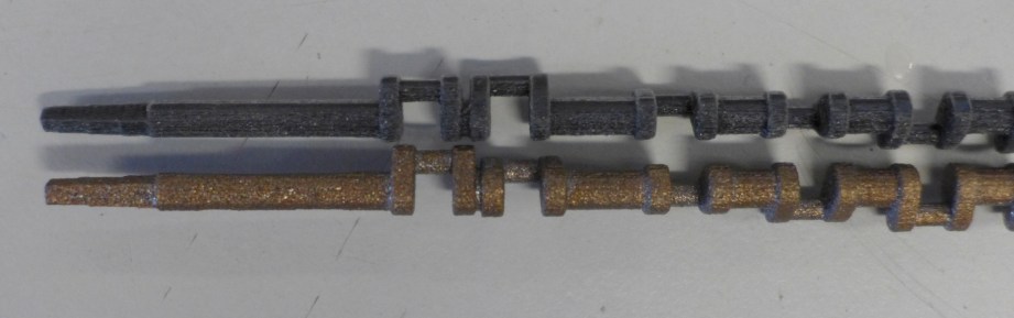
I’m working on a new version of the crankshaft with larger tolerances and higher strength and will be trying another print soon. Ultimately, Adam said that if all else fails he’ll make the crankshaft by hand, at least the 3D printed version is a good guide. Adam was able to finish up a non-running Motivator for the Mecha-Hand reveal at the Tested Incognito party. I was really impressed by how good the Motivator looked after painting and weathering. Now I had to try it myself, but that’s a story for next time!
Designing a Custom Arcade Cabinet in Sketchup
As soon as Norm and I decided to build an arcade cabinet, we ran into a problem: We didn’t actually know how to build an arcade cabinet. We knew what we wanted, at least in general–a four-player MAME cocktail cabinet that could support fighting games and beat ’em ups and pretty much anything else we could throw at it. How hard could it be to find exactly what we wanted online, then replicate it at home? Turns out: Pretty hard.
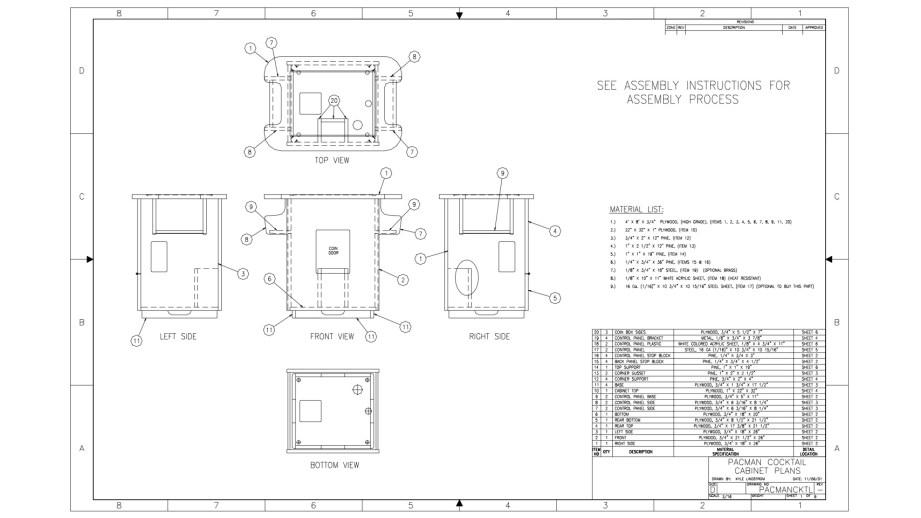
ArcadeDepot, one of the most popular sources for arcade kits, was knocked out of commission by Hurricane Sandy. The other pre-built kits we looked at didn’t offer customization. That left user-built arcade cabinets to work off of. The Arcade Controls forums and wiki are great resources, with one unfortunate downside: Many of the projects linked on the site now lead to 10-year-old dead webpages, and most members only upload photos of their homemade arcade cabinets, sans dimensions or detailed blueprints. That left us with one good option: the detailed Pac-Man cocktail plans and assembly instructions created by Kyle Lindstrom.
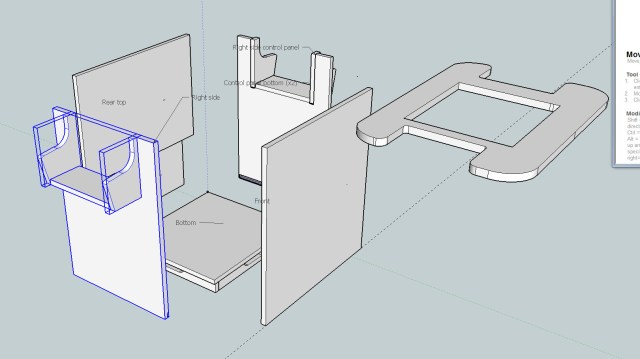
Most cocktail cabinets are heavily based on the original Pac-Man cocktail, with a few tweaks here and an added control panel there to support two extra players. To make those tweaks, I decided to recreate the Pac-Man cocktail cabinet in SketchUp. Once I had a 3D model of each part, it would (hopefully) be easy to piece them together, add another control panel, and change some dimensions while making sure everything still fit together.
After recreating the cocktail cabinet in 3D, the next phase of our build could begin: Creating a cardboard mockup, to make sure the dimensions of our modified design would give us enough control panel room. The cardboard build would also give us a good visualization of how the planned 19-inch arcade monitor would look in a slightly enlarged cabinet.
SketchUp is a free download, and offers templates upon startup to work in millimeters, inches, feet, and so on. I started with inches, and spent a few minutes fiddling with the 3D camera before settling on a top-down perspective. Then I started drawing each Pac-Man cabinet part in 2D.
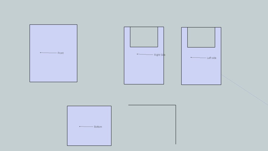
Drawing the Parts
At first, the modeling was slower going than I expected. It’s been about eight years since I last used 3D design software, and I don’t remember much from my high school classes on AutoCAD drafting and 3D Studio Max animation. Even if I did, SketchUp has its own UI to learn. I first tried to draw rectangles and then modify their X/Y coordinates to fit Lindstrom’s dimensions. That didn’t work–once an object is drawn in SketchUp, individual dimensions can’t be modified.
For example, I was working with a rectangle. Because one line/side of the rectangle was attached to two other sides, SketchUp wouldn’t let me change its length. Doing so would require one of those other sides to move, changing the shape of the object. That would’ve been fine with me, since I would’ve changed length, then height. But it wasn’t an option.
SketchUp offers a scaling tool to change the dimensions of whole objects, but that didn’t quite do what I wanted, either. So I settled for the simplest option: Drawing one line, then typing in its exact length, doing the same for the second axis, and then drawing the next two lines to match. Thankfully SketchUp is good about offering snapping guides for straight lines. It didn’t take long to draw all of the rectangular parts. I labeled them along the way to keep track of what was what.
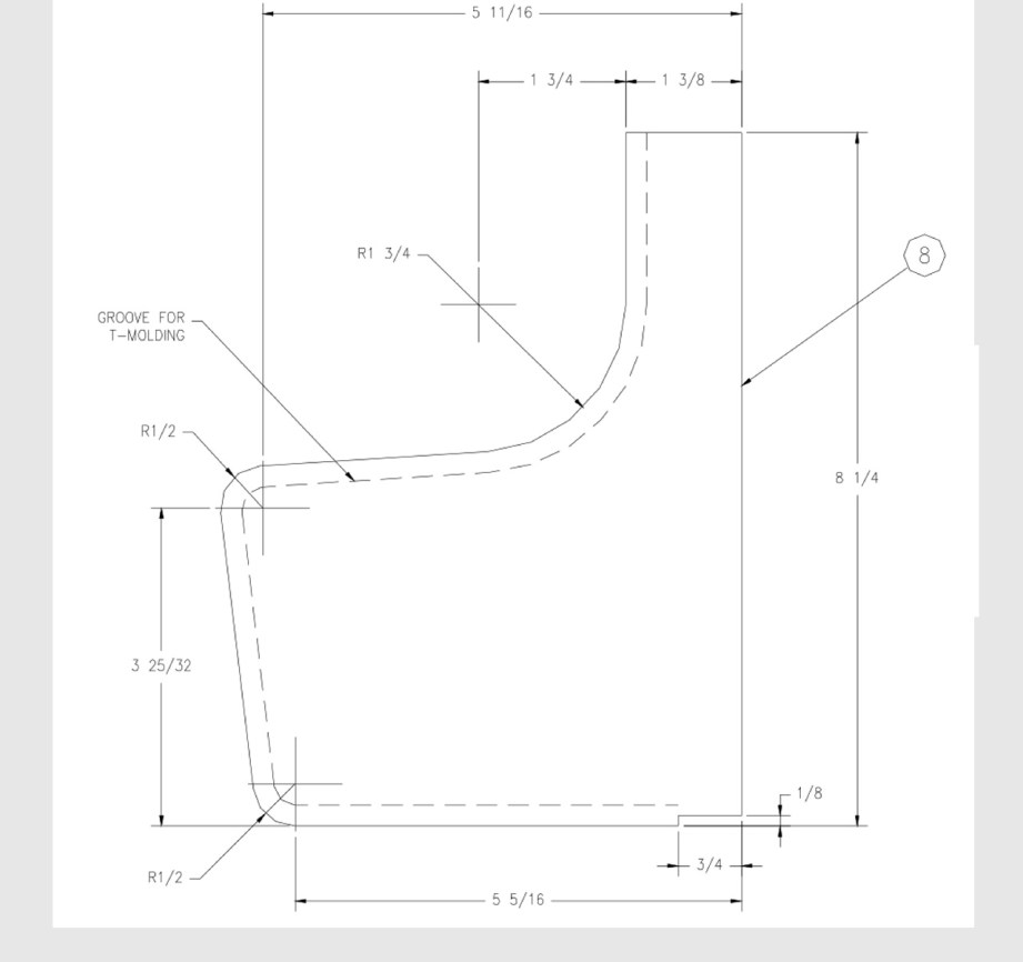
Drawing the top of the cabinet and the curved sides for the control panels was trickier. Those had curves. Instead of trying to perfectly reproduce the curves of the real parts, I decided to eyeball it using SketchUp’s radius tool. We won’t be printing out my 3D models and using them as patterns–the whole point of modeling is simply to give us a base we can work on and modify.
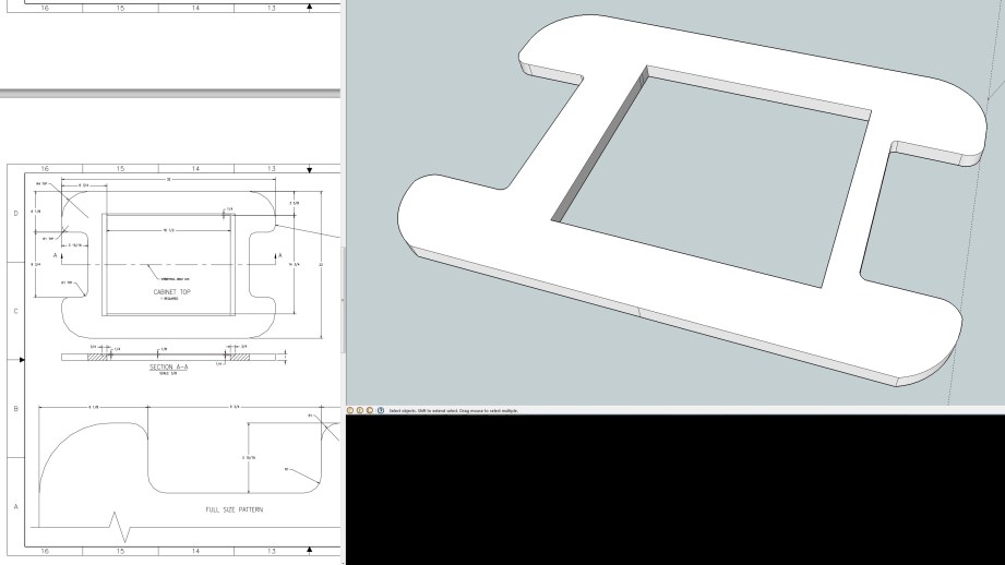
One side of my cabinet top ended up a little wonky, but that’s okay. I only drew one side of the top and mirrored it, when I could’ve drawn the top quarter and done both a horizontal and vertical mirror. But I found mirroring less intuitive in SketchUp than I remembered it from Autodesk software. I had to copy the part, paste a new piece, then flip it along an axis to mirror it, and getting the lines to connect and register a new solid object took a few minutes.
With all of the pieces drawn, it was time to extrude. Again I hit a small snag with SketchUp’s interface: I found the extrude tool, but didn’t know how to specify a distance to stretch my pieces into the Z axis. Instead, I moved the mouse very slowly, watching the numbers in the bottom right corner, where SketchUp displays dimensions, and let go once I hit 3/4-inch. That was the thickness of almost every part in the arcade build. Once everything was nice and 3D, I decided to copy all of my parts and use duplicates to assemble a model. That way, if I wanted to look at a part again, I wouldn’t have to pull it out of the assembly and mess around with the camera.
Digital Assembly
After a few complications, assembling the model turned out to be much easier than I expected. The first embarrassing roadblock I ran into was simply rotating pieces to the orientation I wanted them. Try as I might, I could never get an easy 90 degree rotation along one axis with SketchUp’s rotate tool, which I needed to do to line up the cabinet’s base pieces. A quick Google search led me to exactly what I needed–a Sketchup extension that added 90 degree rotations to the right-click menu. To use the rotation, I had to convert my objects–which were still comprised of individual lines and faces–into components, which are essentially solid grouped objects.

Once I’d converted my objects into components, I realized two cool things. One: Any edits I made to a component would affect every copy I had of that component. This came in handy when I discovered that I needed to make notches in a few pieces so that they would lock into place. Two: Selecting a component’s corner with SketchUp’s move tool allows you to snap that corner to another component’s corner. Once I figured that out, I was able to put together the entire cocktail cabinet in about 15 minutes.
There were only a few parts I didn’t render–internal supports that you can’t see, the coin box we won’t need since we’re building a MAME machine, and the control panels, since I wanted to create custom layouts for those. Adding the player-one-and-two panel to the front of the cabinet was the next step. Since the front panel was 21.5 inches wide, I decided to create a control panel to fit that and allowed for 3/4-inch on each side for supports.
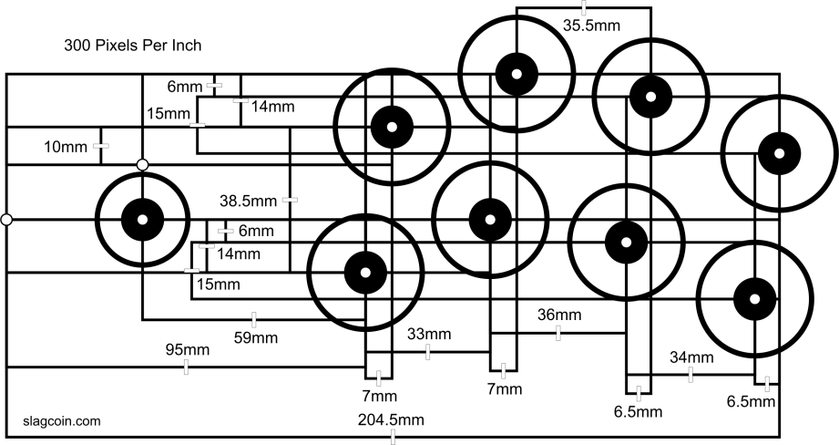
Fitting two joysticks and two six button layouts into that space was going to be a tight fit. Slagcoin, the site I turned to to research joysticks and buttons, also offers this nugget of wisdom about control panel layouts: “A big problem with many designs is there is not a large enough panel in front and on the sides of the devices to rest the hands. In addition to well-organized buttons and joysticks, a large enough empty space of panel should be available to rest the palms.”
Cramming the buttons and joysticks together would’ve offered more space, but I decided on the standard Japanese arcade layout used on Sega’s Astro City cabinets. That meant two curved rows of well-spaced buttons…and not enough room to fit both players comfortably on one panel. To make sure, I even imported Slagcoin’s layout diagrams into SketchUp and sized them to scale.
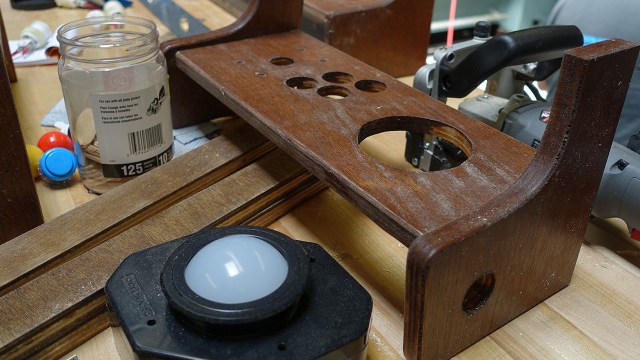
At this point, I essentially had the Pac-Man cocktail cabinet complete to its original specifications. The front panel obviously wasn’t going to be long enough to support two comfortable, properly spaced six button layouts. I also measured the dimensions of Ultimarc’s U-Trak trackball, which is more compact and easier to install than most arcade trackball options–it doesn’t require a giant faceplate to cover up its installation on top of the control panel. At this stage, we weren’t positive if we wanted to install a trackball or not, but if we did, it would be on one of the smaller side control panels. And those definitely didn’t offer enough space for a trackball.
We decided to add four inches to both the long and short sides of the cabinet, while leaving the height the same. To accommodate the possibility of a trackball, I also added an inch to the depth of the control panels, making them six inches deep. I ended up skipping modeling the front control panel, since it wasn’t in the original plans; it would enter the project during the cardboard phase.
Sizing up the existing components helped me figure out a couple SketchUp features that I didn’t get at first. The primary one was using the measurements field in the bottom right corner of the SketchUp window. First, I’d click on a component and use the “Scale” feature to stretch it out horizontally. When I was sizing pieces to the proper dimensions earlier, I didn’t realize I could type the exact dimensions into the Measurements box because it always looks like it was grayed out and disabled. But I could; it just looks disabled.
That didn’t work quite as well with scaling, because the scale tool uses a percentage relative to the original size of the component. With some math, I was able to come up with percentages for the pieces that needed to be scaled up 4 inches–like a factor of 1.33, for example–and precisely resize them. I confirmed the size of each piece with the tape measure tool before reassembling the 3D model.
With a complete 3D model that looked good, it was time to start cutting cardboard.
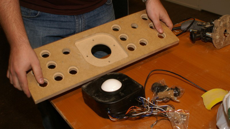
A Mockup with Cardboard
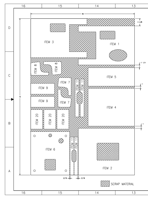
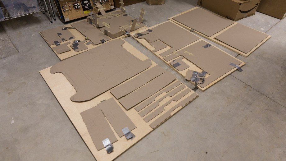
Since we didn’t want to jump straight into woodworking without a good model of what our arcade machine would look like, we bought a stack of 40×48 inch sheets of cardboard from Amazon. To recreate the 3D arcade cabinet, we worked off Kyle Lindstrom’s Pac-Man plans while adding four inches to the appropriate panels.
We drew each piece with a pencil, guestimated on the few curves in the design, and cut pretty quickly with a boxcutter. As a result, most of the pieces weren’t cut perfectly straight or exactly the right dimensions, but they were close enough for a mockup build.
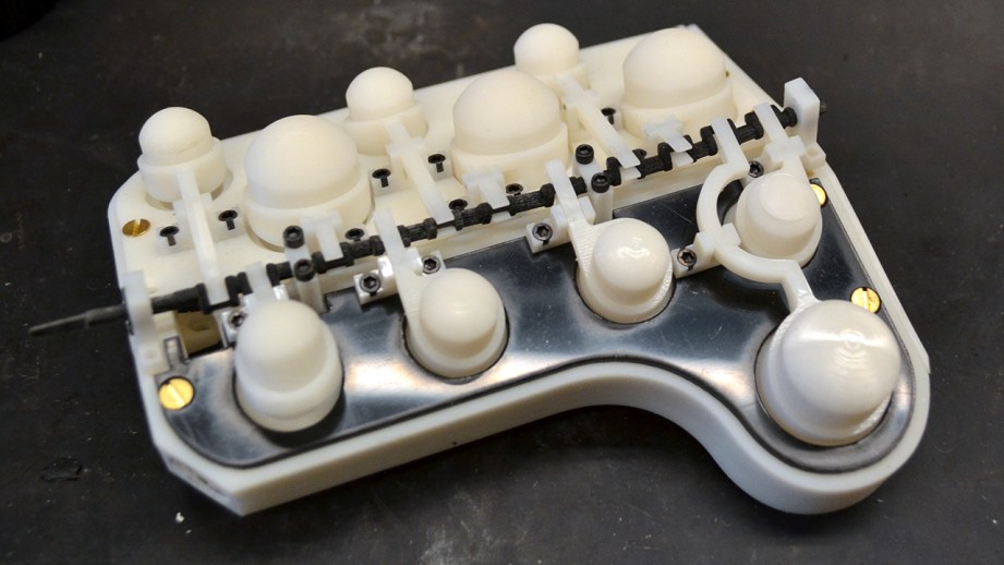
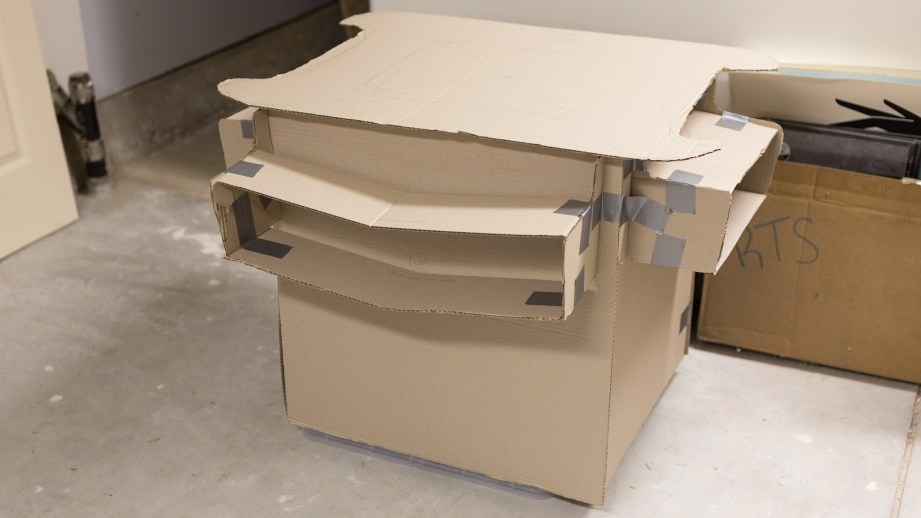
Finally, with all the pieces cut out, it was time to assemble the cardboard into something that looked like an arcade cabinet. While the real deal will be held together with screws and glue, we opted for a simpler tool for the lightweight mockup: Tape. Lots and lots of tape.
To give the sides extra support and hold them together, we cut a bunch of scrap cardboard into strips and taped those to the corners, holding them together with masking tape and duct tape. Because we used cardboard, some of the dimensions weren’t quite right. For example, the side control panel width was designed to fit between two 3/4-inch wood supports. Our cardboard supports weren’t even close to 3/4-inch, so we were left with a gap.
But for the most part, everything fit together surprisingly well. Aside from the saggy front control panel, the cardboard cabinet held itself together and reassured us that the few extra inches we added would do the trick. It was time to buy and cut plywood to build the real thing.
Best Jobs Ever – 8/26/2014

Tested Projects: Building a Custom Arcade Cabinet, Part 1
Our next Tested Project is a custom arcade cabinet, built from scratch! Norm and Tested contributor Wesley Fenlon have been working on a cocktail cabinet build, using designs and recommendations found online. In this introductory episode, we discuss the design of the cabinet and our parts list for building. We also bring in Adam’s friend (and ex-ILM modelmaker) John Duncan to supervise and provide guidance for woodworking in Adam’s shop. (This video was brought to you by Premium memberships on Tested. Learn more about how you can support us with memberships!)
Video shot and edited by Joey Fameli
Episode 268 – Listener’s Choice/Rumor Mill – 8/21/2014
Adam Savage’s Alien Spacesuit Replica
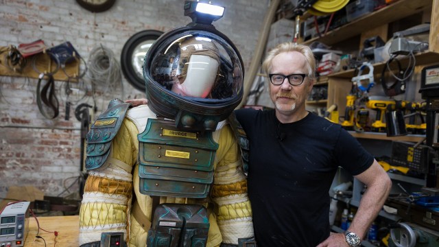
Before we went to Comic-Con, we visited Adam in his shop to get an up close look at his replica ‘Kane’ spacesuit from Alien. At this point, Adam was just about to complete the 10-year project of building the suit in anticipation for his Incognito walk at SDCC. Here, he describes each of the unique components he obsessed over fabricating in this dream project.
Shot and edited by Joey Fameli
Bits to Atoms: Building the Millenbaugh Motivator, Part 3
Progress on the Millenbaugh Motivator marches on! All the measurements have been made and a rough version has been modeled and approved by Adam. This week we take a look at modeling the final version and speccing hardware.
I decided to tackle the ‘valve arms’ first since I wasn’t sure how to build them. They look relatively simple but on closer inspection there’s multiple compound curves, plus the forked portion at the back and I couldn’t easily build them using my regular techniques. I ended up drawing them as 2D splines (curve described by interpreting points) on top of the reference photo–if you are comfortable using the pen tool in Illustrator or Photoshop, this is the same idea. I was able to give the spline thickness by extruding it and then used planes and simple shapes to cut out the rear fork and the front slope.
Early on, it was tough picturing the size of some of the parts. When you’re constantly looking at blown up pictures for reference and working in 3D where things are floating in space, you start to picture things much bigger than they really are. Adam mentions this in our video when he was convinced the motivator was too small until he actually placed it on the glove. I did a test print on my MakerBot and it looked way too small, so I printed a 1:1 reference picture to easily compare parts and they were right on. I was even able to print the pivot and if a part was printable on the MakerBot (even if it was a little rough) it should print on the high-end printer without any problems.
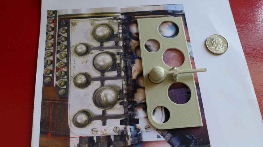
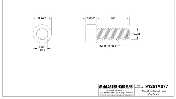
Initially, Adam told me he would spec out all the actual hardware–screws, nuts, bearings, etc., but after the first test print I realized it would be easier for me to do it. I needed to know the exact fastener sizes in order to build the parts around them. Using the Photoshop measurements I picked an approximate fastener size and confirmed it using the free CAD files that McMaster-Carr supplies. I was also able to use the CAD files to import 3D models of all the hardware into Cinema 4D which made things much easier.
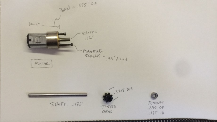
Adam was still supplying the drive mechanism for the Motivator and sent me great reference pictures of the motor, chain and bearings. I used that info to build a stand-in for the motor so I could print it out and test it with the motor mount. I used the same spline technique to build the main blocks and top plates and was able to include all the holes needed for the hardware. That gave me the basic shape for the blocks, but the valve hollows and all the details underneath needed to be cut out separately, which required many steps. If I needed to modify something I would often have to go back to the base version, tweak it and then do all the steps to cut everything out again.
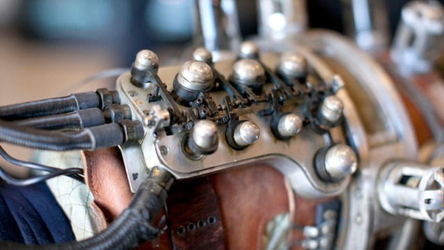
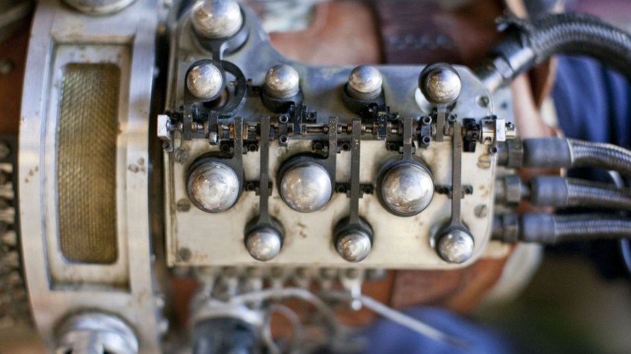
Adam reminded me to not forget the LED lights and I was like, ‘what lights?’ since I had not seen any on the reference pictures. Adam said there was an LED underneath each valve so I had to shuffle things around a bit to accommodate those. Later, when Adam sent me a video he shot of the motivator running, there was indeed an LED under one of the valves, but the rest were dark. I heard him comment to the operator that the LED looked cool. The operator said it was just the operating light from the speed control and I think Adam liked the look and made a nice modification.
Demo video at Spectral Motion showing the firing order and the elusive LED. CREDIT: Adam Savage
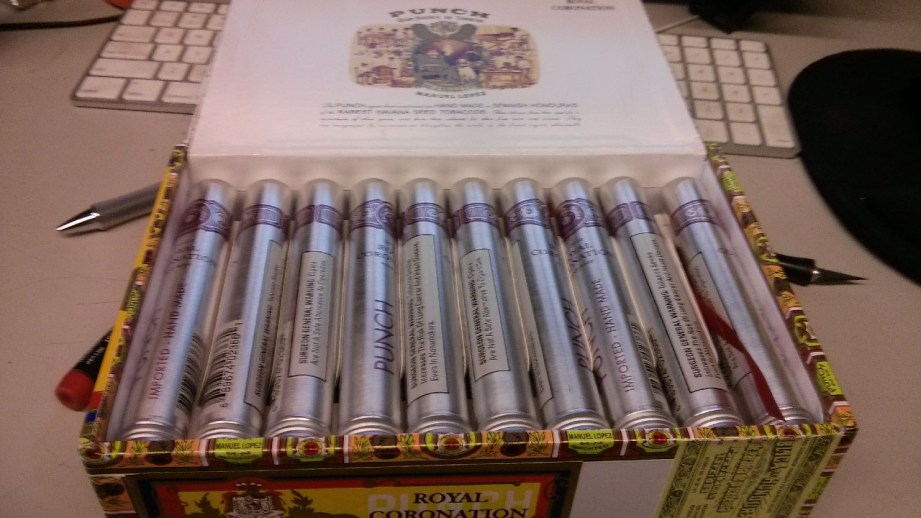
Adam had an epiphany–he realized that the valve dome looked just like the end of a cigar tube.
Things were progressing well–I was up to version 3 of the main block–and Adam had an epiphany. He realized that the valve dome looked just like the end of a cigar tube so why not use those instead! I was game, so my wife and I spent a Saturday afternoon going to eight different NYC cigar shops in search of the perfect cigar tube. Explaining that I needed their crappiest cigar that came in a metal tube about ‘this big’– and then pulling out a pair of calipers was fun.
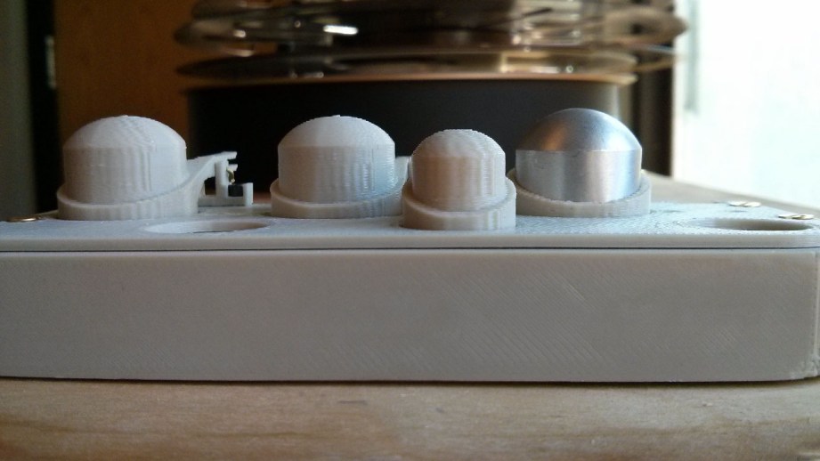
We finally found a suitable tube for the large dome but they ran $12 each and since we were building three motivators that was $150 worth of cigar tubes, not counting the small domes! Thanks to the research skills of Mrs. Charlesworth, we learned a lot about cigar sizes, types of cigars and cigar cases (thanks Reddit!) and ultimately discovered that cigar tubes don’t come in the size needed for the small domes. Adam still wanted to forge ahead, he figured the large tubes would save him some work and he would lathe the small ones. I was able to track down a 30 count box of the right cigars for much cheaper online and Adam sent them my way. And since neither Adam nor I smoke and he just wanted the tubes, my father-in-law became the very happy owner of a bunch of tubeless cigars.
Eventually, Adam sent me the actual motor, drive chain and bearings so I could do a test assembly before the final prints. The real motor differed slightly from my stand-in, so further modifications were needed–it was a really tight fit, but I was able to squeeze it in along with an adjustable motor mount. Everything was lining up and I finally had to build what I had been dreading–the crankshaft.
To design the crankshaft, I needed to figure out the firing order of the valves and used the same video that the LEDs showed up in. Going frame-by-frame, I figured out the correct order and started laying out the crankshaft. I posed each valve in it’s firing order, created an offset (crank pin) for one valve and copied it for all the others, adjusting the rotation as needed. The clearances were so tight that I often had problems with the back of the arms hitting the block or the crank pin popping out of the arm. You could see from the reference photos that they had similar problems on the original. The curved arm is a great example as you can see they soldered a cap on the end because the crank pin was popping out.
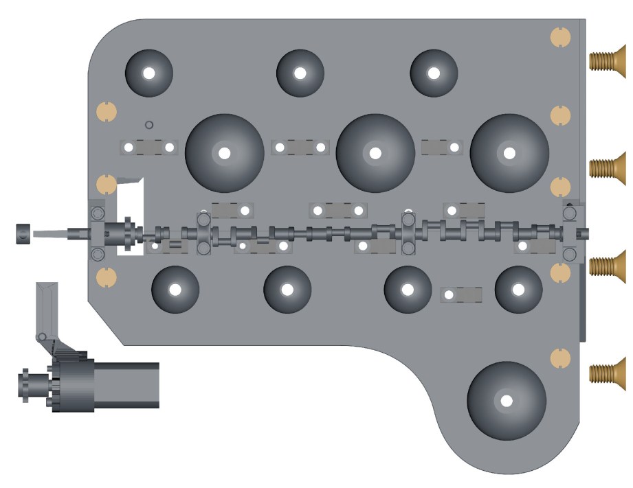
I thought I was finished and tested the crankshaft by rotating it within the program only to discover that it rammed right into the arm pivots on the right side block. Oh boy. There’s only so many measurements you can get from the reference pictures and I assumed that the crankshaft was centered on the seam between the two blocks – it wasn’t. I needed to move the whole thing back toward the left which set off a week of revisions. In order to move the crankshaft, I had to move the crankshaft mounts, which required changes to the blocks, which messed up the alignment of other hardware that had to be tweaked – it was a nightmare. This is a good example where CAD modeling may be the better choice since it’s meant for mechanical modeling and even simulating mechanisms.
I finally got the crankshaft laid out, but it needed a final test print before dropping the big bucks on the fancy printer. Up until this point, the MakerBot had managed to print everything but the crankshaft was just too small, spindly and precise to print properly. I tried every trick in the book including printing with support material.
I also have a dual head machine so I can print ABS plastic on one extruder and HIPS support material on the other. HIPS plastic can be dissolved in limonene–a citrus based product–which won’t affect the ABS. The ABS model is encased in the HIPS support, making for a much better print. Alas, even this didn’t work, the crankshaft needed too much precision, was too delicate and didn’t turn out well.
Crankshaft problems aside, I was able to print the rest of the Motivator and assemble it successfully. All the hardware worked, the motor fit and could be adjusted, and there was enough room for electronics. Adam told me to make sure to sign it in some way. In the movie, Rasputin used the Mecha-Hand to release Hellboy in 1944, so I figured that Charlesworth Dynamics finished the motivator a few years prior in 1942. Having finished a complete prototype, Charlesworth Dynamics shipped it off to Adam for approval. After a test-fit on the Mecha-Hand, Adam gave the go ahead, so we were all set for the final print!
Tune in next week for the final print, assembly and the Motivator tested under full power!
- Part 1 – Becoming The Inventern
- Part 2 – Reference & Measurements
- Part 3 – Prototypes
- Part 4 – Final Print
- Part 5 – Finishing Work
All photos courtesy Sean Charlesworth unless otherwise indicated.
Zoidberg Jesus at Comic-Con!

We love going to Comic-Con, but have noticed that every year there are some picketers outside that take a little bit of the fun away from going to these fan events. We decided to bring the fun back by introducing them to our friend, Zoidberg Jesus.
Video shot and edited by Joey Fameli