Stanley Kubrick Exhibit at The LACMA
Photo Gallery: Exhibit entrance
Since last November, the Los Angeles County Museum of Art has been home to a special travelling exhibit documenting the late Stanley Kubrick’s movies, photographs, and personal projects. That exhibition concludes at the end of this month, so I drove down to LA this past weekend to see it before it moves to its next destination (it has been on tour all around the world since debuting in Germany in 2004). Among the items on display: iconic film props, production memorabilia, camera lenses Kubrick favored, and even early scripts with Kubrick’s handwritten annotations. Here are some of my photos from the exhibition. (A few photos NSFW)
Stanley Kubrick Exhibit at The LACMA
Photo Gallery: Kubrick’s Directors Chair
Since last November, the Los Angeles County Museum of Art has been home to a special travelling exhibit documenting the late Stanley Kubrick’s movies, photographs, and personal projects. That exhibition concludes at the end of this month, so I drove down to LA this past weekend to see it before it moves to its next destination (it has been on tour all around the world since debuting in Germany in 2004). Among the items on display: iconic film props, production memorabilia, camera lenses Kubrick favored, and even early scripts with Kubrick’s handwritten annotations. Here are some of my photos from the exhibition. (A few photos NSFW)
Stanley Kubrick Exhibit at The LACMA
Photo Gallery: Kubrick Exhibit
Since last November, the Los Angeles County Museum of Art has been home to a special travelling exhibit documenting the late Stanley Kubrick’s movies, photographs, and personal projects. That exhibition concludes at the end of this month, so I drove down to LA this past weekend to see it before it moves to its next destination (it has been on tour all around the world since debuting in Germany in 2004). Among the items on display: iconic film props, production memorabilia, camera lenses Kubrick favored, and even early scripts with Kubrick’s handwritten annotations. Here are some of my photos from the exhibition. (A few photos NSFW)
Stanley Kubrick Exhibit at The LACMA
Photo Gallery: Posters of Kubrick’s Films
Since last November, the Los Angeles County Museum of Art has been home to a special travelling exhibit documenting the late Stanley Kubrick’s movies, photographs, and personal projects. That exhibition concludes at the end of this month, so I drove down to LA this past weekend to see it before it moves to its next destination (it has been on tour all around the world since debuting in Germany in 2004). Among the items on display: iconic film props, production memorabilia, camera lenses Kubrick favored, and even early scripts with Kubrick’s handwritten annotations. Here are some of my photos from the exhibition. (A few photos NSFW)
Stanley Kubrick Exhibit at The LACMA
Photo Gallery: Lolita Poster
Since last November, the Los Angeles County Museum of Art has been home to a special travelling exhibit documenting the late Stanley Kubrick’s movies, photographs, and personal projects. That exhibition concludes at the end of this month, so I drove down to LA this past weekend to see it before it moves to its next destination (it has been on tour all around the world since debuting in Germany in 2004). Among the items on display: iconic film props, production memorabilia, camera lenses Kubrick favored, and even early scripts with Kubrick’s handwritten annotations. Here are some of my photos from the exhibition. (A few photos NSFW)
Stanley Kubrick Exhibit at The LACMA
Photo Gallery: Posters of Kubrick’s Films
Since last November, the Los Angeles County Museum of Art has been home to a special travelling exhibit documenting the late Stanley Kubrick’s movies, photographs, and personal projects. That exhibition concludes at the end of this month, so I drove down to LA this past weekend to see it before it moves to its next destination (it has been on tour all around the world since debuting in Germany in 2004). Among the items on display: iconic film props, production memorabilia, camera lenses Kubrick favored, and even early scripts with Kubrick’s handwritten annotations. Here are some of my photos from the exhibition. (A few photos NSFW)
Stanley Kubrick Exhibit at The LACMA
Photo Gallery: Kubrick Exhibit
Since last November, the Los Angeles County Museum of Art has been home to a special travelling exhibit documenting the late Stanley Kubrick’s movies, photographs, and personal projects. That exhibition concludes at the end of this month, so I drove down to LA this past weekend to see it before it moves to its next destination (it has been on tour all around the world since debuting in Germany in 2004). Among the items on display: iconic film props, production memorabilia, camera lenses Kubrick favored, and even early scripts with Kubrick’s handwritten annotations. Here are some of my photos from the exhibition. (A few photos NSFW)
Stanley Kubrick Exhibit at The LACMA
Photo Gallery: Kubrick Exhibit
Since last November, the Los Angeles County Museum of Art has been home to a special travelling exhibit documenting the late Stanley Kubrick’s movies, photographs, and personal projects. That exhibition concludes at the end of this month, so I drove down to LA this past weekend to see it before it moves to its next destination (it has been on tour all around the world since debuting in Germany in 2004). Among the items on display: iconic film props, production memorabilia, camera lenses Kubrick favored, and even early scripts with Kubrick’s handwritten annotations. Here are some of my photos from the exhibition. (A few photos NSFW)
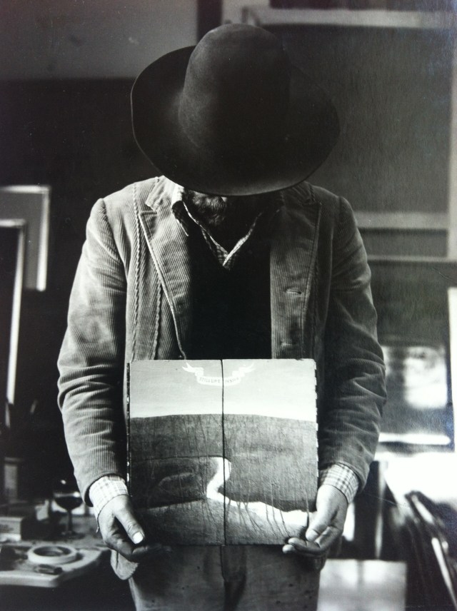
Stanley Kubrick Exhibit at The LACMA
Photo Gallery: Kubrick as a Photographer
Since last November, the Los Angeles County Museum of Art has been home to a special travelling exhibit documenting the late Stanley Kubrick’s movies, photographs, and personal projects. That exhibition concludes at the end of this month, so I drove down to LA this past weekend to see it before it moves to its next destination (it has been on tour all around the world since debuting in Germany in 2004). Among the items on display: iconic film props, production memorabilia, camera lenses Kubrick favored, and even early scripts with Kubrick’s handwritten annotations. Here are some of my photos from the exhibition. (A few photos NSFW)
Stanley Kubrick Exhibit at The LACMA
Photo Gallery: Kubrick Exhibit
Since last November, the Los Angeles County Museum of Art has been home to a special travelling exhibit documenting the late Stanley Kubrick’s movies, photographs, and personal projects. That exhibition concludes at the end of this month, so I drove down to LA this past weekend to see it before it moves to its next destination (it has been on tour all around the world since debuting in Germany in 2004). Among the items on display: iconic film props, production memorabilia, camera lenses Kubrick favored, and even early scripts with Kubrick’s handwritten annotations. Here are some of my photos from the exhibition. (A few photos NSFW)
Stanley Kubrick Exhibit at The LACMA
Photo Gallery: Kubrick’s Camera Lenses
Since last November, the Los Angeles County Museum of Art has been home to a special travelling exhibit documenting the late Stanley Kubrick’s movies, photographs, and personal projects. That exhibition concludes at the end of this month, so I drove down to LA this past weekend to see it before it moves to its next destination (it has been on tour all around the world since debuting in Germany in 2004). Among the items on display: iconic film props, production memorabilia, camera lenses Kubrick favored, and even early scripts with Kubrick’s handwritten annotations. Here are some of my photos from the exhibition. (A few photos NSFW)
Stanley Kubrick Exhibit at The LACMA
Photo Gallery: Kubrick Exhibit
Since last November, the Los Angeles County Museum of Art has been home to a special travelling exhibit documenting the late Stanley Kubrick’s movies, photographs, and personal projects. That exhibition concludes at the end of this month, so I drove down to LA this past weekend to see it before it moves to its next destination (it has been on tour all around the world since debuting in Germany in 2004). Among the items on display: iconic film props, production memorabilia, camera lenses Kubrick favored, and even early scripts with Kubrick’s handwritten annotations. Here are some of my photos from the exhibition. (A few photos NSFW)
Stanley Kubrick Exhibit at The LACMA
Photo Gallery: Dr. Strangelove
Since last November, the Los Angeles County Museum of Art has been home to a special travelling exhibit documenting the late Stanley Kubrick’s movies, photographs, and personal projects. That exhibition concludes at the end of this month, so I drove down to LA this past weekend to see it before it moves to its next destination (it has been on tour all around the world since debuting in Germany in 2004). Among the items on display: iconic film props, production memorabilia, camera lenses Kubrick favored, and even early scripts with Kubrick’s handwritten annotations. Here are some of my photos from the exhibition. (A few photos NSFW)
Stanley Kubrick Exhibit at The LACMA
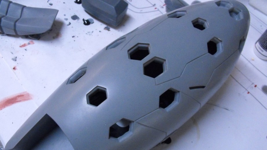
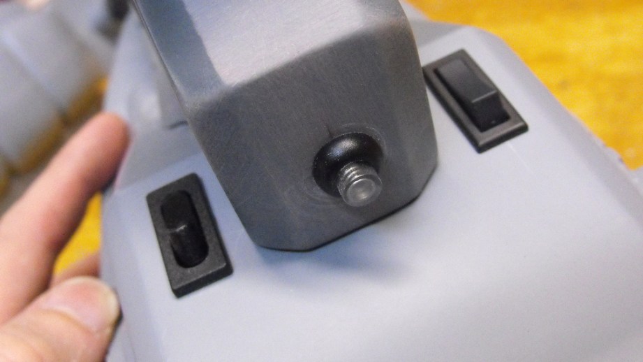
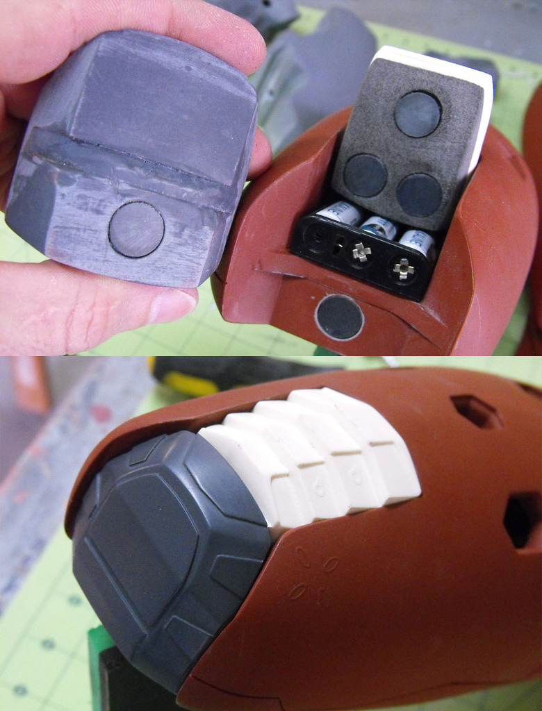
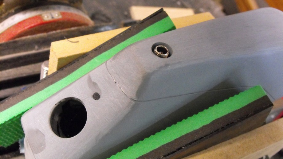
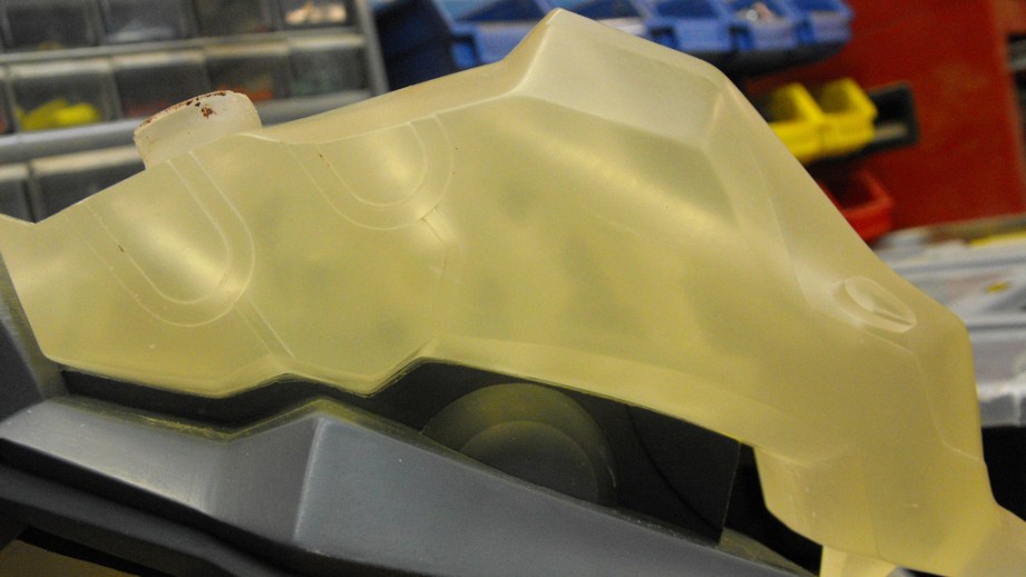
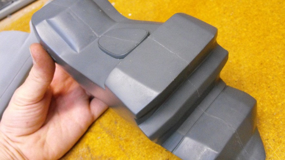
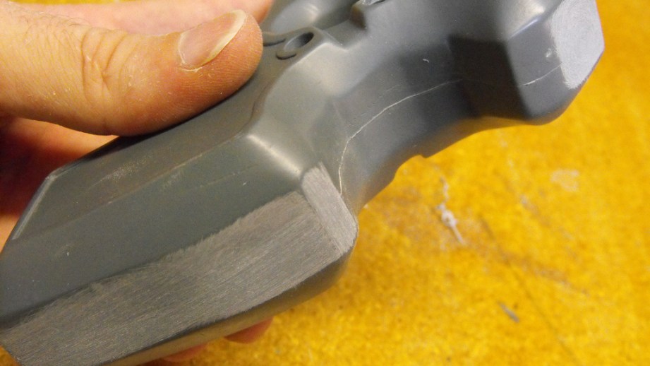
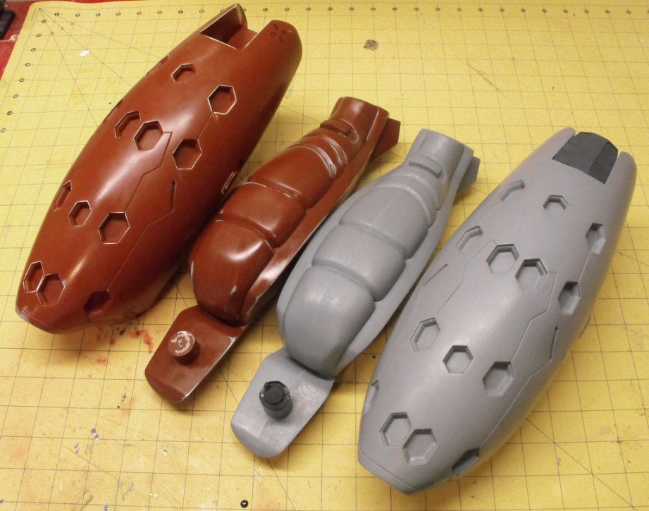
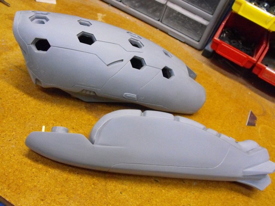
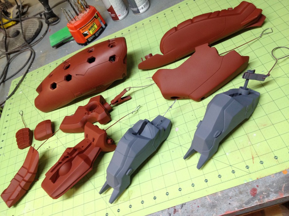
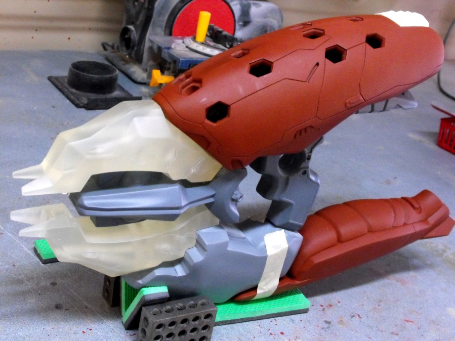
Photo Gallery: 2001: A Space Odyssey
Since last November, the Los Angeles County Museum of Art has been home to a special travelling exhibit documenting the late Stanley Kubrick’s movies, photographs, and personal projects. That exhibition concludes at the end of this month, so I drove down to LA this past weekend to see it before it moves to its next destination (it has been on tour all around the world since debuting in Germany in 2004). Among the items on display: iconic film props, production memorabilia, camera lenses Kubrick favored, and even early scripts with Kubrick’s handwritten annotations. Here are some of my photos from the exhibition. (A few photos NSFW)
Stanley Kubrick Exhibit at The LACMA
Photo Gallery: Kubrick Exhibit
Since last November, the Los Angeles County Museum of Art has been home to a special travelling exhibit documenting the late Stanley Kubrick’s movies, photographs, and personal projects. That exhibition concludes at the end of this month, so I drove down to LA this past weekend to see it before it moves to its next destination (it has been on tour all around the world since debuting in Germany in 2004). Among the items on display: iconic film props, production memorabilia, camera lenses Kubrick favored, and even early scripts with Kubrick’s handwritten annotations. Here are some of my photos from the exhibition. (A few photos NSFW)
Stanley Kubrick Exhibit at The LACMA
Photo Gallery: A Clockwork Orange
Since last November, the Los Angeles County Museum of Art has been home to a special travelling exhibit documenting the late Stanley Kubrick’s movies, photographs, and personal projects. That exhibition concludes at the end of this month, so I drove down to LA this past weekend to see it before it moves to its next destination (it has been on tour all around the world since debuting in Germany in 2004). Among the items on display: iconic film props, production memorabilia, camera lenses Kubrick favored, and even early scripts with Kubrick’s handwritten annotations. Here are some of my photos from the exhibition. (A few photos NSFW)
Stanley Kubrick Exhibit at The LACMA
Photo Gallery: The Shining
Since last November, the Los Angeles County Museum of Art has been home to a special travelling exhibit documenting the late Stanley Kubrick’s movies, photographs, and personal projects. That exhibition concludes at the end of this month, so I drove down to LA this past weekend to see it before it moves to its next destination (it has been on tour all around the world since debuting in Germany in 2004). Among the items on display: iconic film props, production memorabilia, camera lenses Kubrick favored, and even early scripts with Kubrick’s handwritten annotations. Here are some of my photos from the exhibition. (A few photos NSFW)
Stanley Kubrick Exhibit at The LACMA
Photo Gallery: Eyes Wide Shut
Since last November, the Los Angeles County Museum of Art has been home to a special travelling exhibit documenting the late Stanley Kubrick’s movies, photographs, and personal projects. That exhibition concludes at the end of this month, so I drove down to LA this past weekend to see it before it moves to its next destination (it has been on tour all around the world since debuting in Germany in 2004). Among the items on display: iconic film props, production memorabilia, camera lenses Kubrick favored, and even early scripts with Kubrick’s handwritten annotations. Here are some of my photos from the exhibition. (A few photos NSFW)
Stanley Kubrick Exhibit at The LACMA
Photo Gallery: Kubrick Exhibit
Since last November, the Los Angeles County Museum of Art has been home to a special travelling exhibit documenting the late Stanley Kubrick’s movies, photographs, and personal projects. That exhibition concludes at the end of this month, so I drove down to LA this past weekend to see it before it moves to its next destination (it has been on tour all around the world since debuting in Germany in 2004). Among the items on display: iconic film props, production memorabilia, camera lenses Kubrick favored, and even early scripts with Kubrick’s handwritten annotations. Here are some of my photos from the exhibition. (A few photos NSFW)
Stanley Kubrick Exhibit at The LACMA
Photo Gallery: Spartacus
Since last November, the Los Angeles County Museum of Art has been home to a special travelling exhibit documenting the late Stanley Kubrick’s movies, photographs, and personal projects. That exhibition concludes at the end of this month, so I drove down to LA this past weekend to see it before it moves to its next destination (it has been on tour all around the world since debuting in Germany in 2004). Among the items on display: iconic film props, production memorabilia, camera lenses Kubrick favored, and even early scripts with Kubrick’s handwritten annotations. Here are some of my photos from the exhibition. (A few photos NSFW)
Stanley Kubrick Exhibit at The LACMA
Photo Gallery: Kubrick Exhibit
Since last November, the Los Angeles County Museum of Art has been home to a special travelling exhibit documenting the late Stanley Kubrick’s movies, photographs, and personal projects. That exhibition concludes at the end of this month, so I drove down to LA this past weekend to see it before it moves to its next destination (it has been on tour all around the world since debuting in Germany in 2004). Among the items on display: iconic film props, production memorabilia, camera lenses Kubrick favored, and even early scripts with Kubrick’s handwritten annotations. Here are some of my photos from the exhibition. (A few photos NSFW)
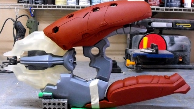
Stanley Kubrick Exhibit at The LACMA
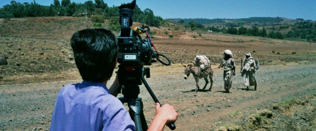
Photo Gallery: Full Metal Jacket
Since last November, the Los Angeles County Museum of Art has been home to a special travelling exhibit documenting the late Stanley Kubrick’s movies, photographs, and personal projects. That exhibition concludes at the end of this month, so I drove down to LA this past weekend to see it before it moves to its next destination (it has been on tour all around the world since debuting in Germany in 2004). Among the items on display: iconic film props, production memorabilia, camera lenses Kubrick favored, and even early scripts with Kubrick’s handwritten annotations. Here are some of my photos from the exhibition. (A few photos NSFW)
Stanley Kubrick Exhibit at The LACMA
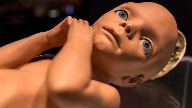
Photo Gallery: A.I.
Since last November, the Los Angeles County Museum of Art has been home to a special travelling exhibit documenting the late Stanley Kubrick’s movies, photographs, and personal projects. That exhibition concludes at the end of this month, so I drove down to LA this past weekend to see it before it moves to its next destination (it has been on tour all around the world since debuting in Germany in 2004). Among the items on display: iconic film props, production memorabilia, camera lenses Kubrick favored, and even early scripts with Kubrick’s handwritten annotations. Here are some of my photos from the exhibition. (A few photos NSFW)
Stanley Kubrick Exhibit at The LACMA
Photo Gallery: Barry Lyndon
Since last November, the Los Angeles County Museum of Art has been home to a special travelling exhibit documenting the late Stanley Kubrick’s movies, photographs, and personal projects. That exhibition concludes at the end of this month, so I drove down to LA this past weekend to see it before it moves to its next destination (it has been on tour all around the world since debuting in Germany in 2004). Among the items on display: iconic film props, production memorabilia, camera lenses Kubrick favored, and even early scripts with Kubrick’s handwritten annotations. Here are some of my photos from the exhibition. (A few photos NSFW)