This week, Will and Norm discuss cooking with water baths, testing high speed cameras, the news from Mobile World Congress in Barcelona, and a whole lot more. Enjoy!
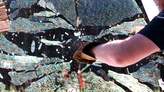
Premium: Setting Up the High-Speed Camera Test
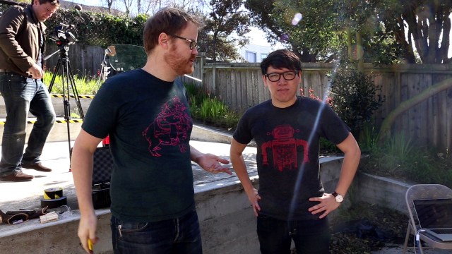
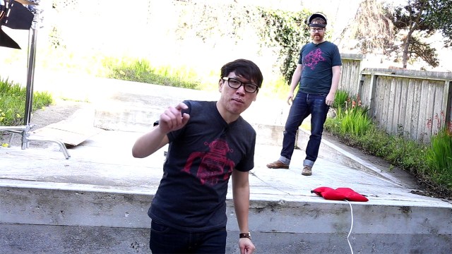
Watch us prep for the video shoot in this behind-the-scenes video! This was the first setup for our day of high-speed camera testing. We only had three side windows to shatter, so getting the lighting and camera focus right was important. Of course, not everything worked as planned.
The Space Shuttle’s Controversial Launch Abort Plan
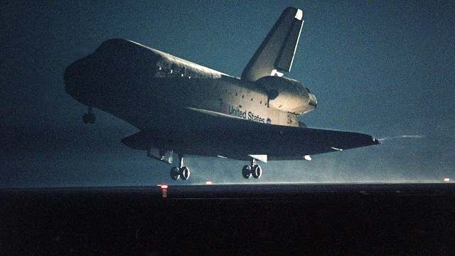
Just about every aspect of spaceflight harbors dangers that are both obvious and concealed. Yet, it is launch and landing that create the most white knuckles and bated breaths. These concerns are well-founded. Getting into orbit requires harnessing unfathomable quantities of volatile energy with laser beam precision. Coming home necessitates somehow dissipating a similar volume of energy within comparably narrow margins of error. As risky as those two endeavors may seem, one NASA plan for the Space Shuttle combined launch and landing into a single 25-minute ride with presumed risks that far exceeded the sum of its parts: the Return To Launch Site (RTLS) abort.
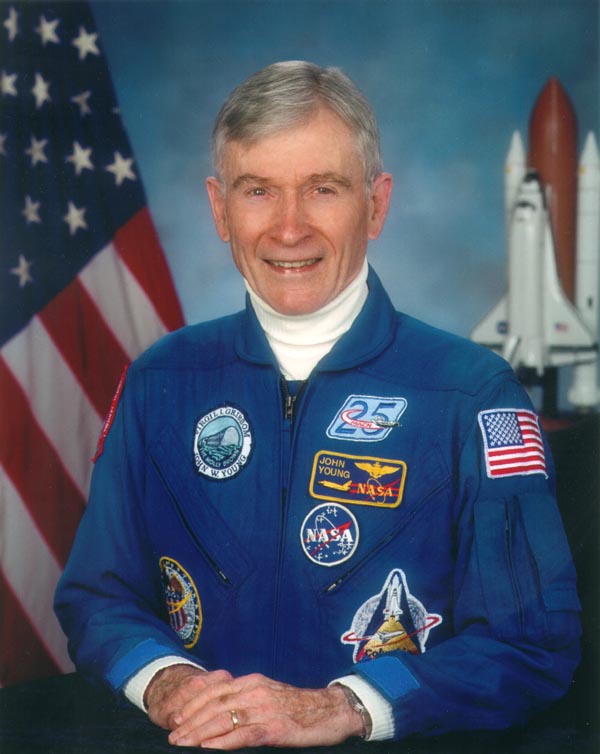
As the name implies, RTLS was a plan to land a malfunctioning Space Shuttle on the runway at Kennedy Space Center (KSC) in the shadow of the launch pad that it recently departed. It sounds easy, right? Surely, it’s just like going back home to make sure you turned off the oven. In actuality, there is much more to it than that. Throughout the Shuttle program’s 30-plus years, there was continuous debate over the validity of the RTLS scenario. Skeptics claimed that the RTLS checklist was nothing more than busywork to distract the astronauts as they rode out an irreversible doom. Even the man who commanded the first Space Shuttle flight (STS-1), astronaut John Young, expressed that “RTLS requires continuous miracles interspersed with acts of God to be successful.”
The good news is that the shuttle’s retirement has made the RTLS argument merely an academic one. Of the 135 Space Shuttle launches, only one (STS-51F on 7/29/85) experienced an abort-inducing failure during ascent. In the case of 51F, they safely made a lower-than-planned orbit and carried out the mission. All of the other flights cleanly avoided the dubious honor of settling the RTLS bet.
An Abort for (Almost) Every Occasion
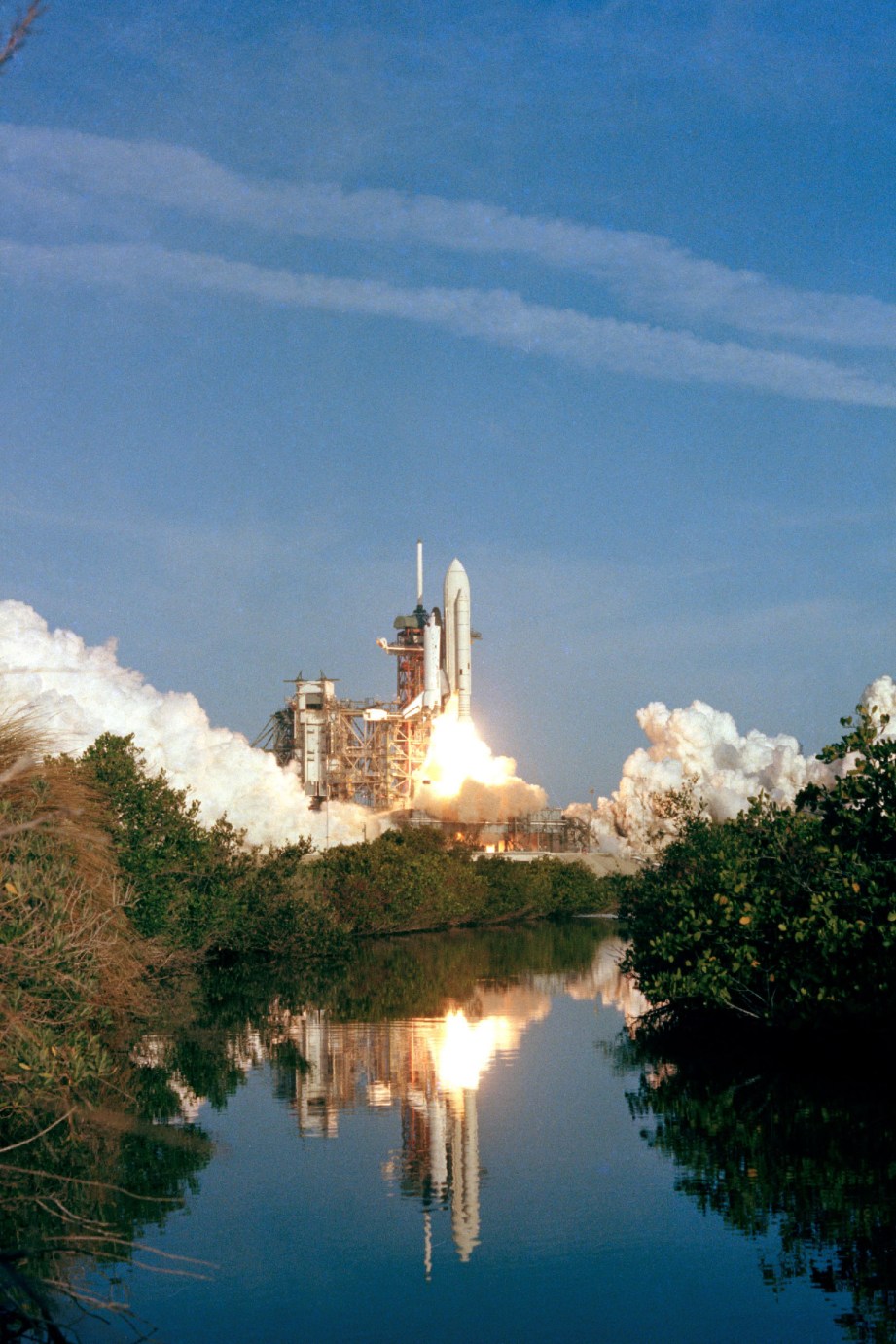
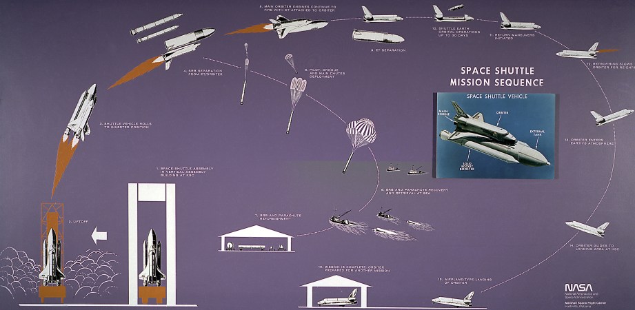
Before we dissect the RTLS scenario, an overview of the nominal launch sequence and the entire abort menu is prudent. At “T minus 6 seconds”, the three Space Shuttle Main Engines (SSME) began burning liquid oxygen and liquid hydrogen from the huge External Tank (ET) attached to the orbiter’s belly. When the countdown reached 0, the SSMEs would be at full power and the two Solid Rocket Boosters (SRB) straddling the ET would ignite to initiate liftoff.
About two minutes into the flight, the SRBs would burn out and then be jettisoned. The SSMEs would continue to burn fuel from the ET until about eight and a half minutes after liftoff. For missions with a particularly heavy payload, the two Orbital Maneuvering System (OMS) engines could be fired during ascent to help the shuttle aloft. The OMS engines were also used later to adjust the shuttle’s orbit, including the deorbit burn that brought it home at the end of the mission. After Main Engine Cutoff (MECO), the shuttle would jettison the empty ET, which would disintegrate as it tumbled back to Earth. That’s all there was to it. What could possibly go wrong?
Well, plenty.
Once the shuttle departed the launch pad, an abort could be triggered either by a problem with one (or more) of the SSMEs, an Auxiliary Power Unit (APU) failure, a pressure leak in the crew cabin, or a fuel leak in the ET, among a list of other undesirable gremlins. The shuttle’s location and energy state at the time of the failure, as well as the severity of the problem, would dictate the type of abort that was declared.
Other than RTLS, mission control had three primary abort options at their disposal: Transoceanic Abort Landing (TAL), Abort Once Around (AOA), and Abort to Orbit (ATO). Along with RTLS, these were considered intact aborts; meaning that the crew had a planned and practiced path to safely land the orbiter and its cargo (including themselves) somewhere in the world. If conditions did not permit any of the intact aborts, or if additional failures occurred, the next option would have been a contingency abort. Basically, the crew would have parachuted or ditched in the ocean…neither of those being cozy options.
One exception among contingency abort options was the East Coast Abort Landing (ECAL). In this case, the crew had a handful of runway-equipped landing sites along the North American east coast (or Bermuda) to set the bird down. The problem was that these locations were less than ideal to handle the needs of a distressed Space Shuttle with only one shot at landing. I suppose that any runway looks inviting when your alternative is a long swim in the Atlantic.
Other than RTLS, mission control had three primary abort options at their disposal: Transoceanic Abort Landing (TAL), Abort Once Around (AOA), and Abort to Orbit (ATO).
A TAL abort could be declared sometime after about two and a half minutes into the launch. At this point, the shuttle would have sufficient fuel to cross the Atlantic Ocean and glide into one of the preselected landing sites in Europe or Africa. If you were ever confused by weather-related launch delays when KSC had clear skies, bad weather at potential TAL landing sites could have been the culprit.
Later in the launch, there was a very narrow window (just a few seconds) to declare an AOA abort. In this scenario, the shuttle would come in for a landing after a single orbit of the earth. This option would be chosen if the shuttle didn’t have sufficient energy to attain a stable orbit, or an issue with a life support system necessitated a quick return. It was generally considered a very low probability that AOA would ever be utilized.
ATO was chosen if a failure occurred late in the ascent and the shuttle had attained enough velocity to reach any stable orbit…not necessarily the planned orbit. This was the case with mission STS-51F that I mentioned earlier (a launch worthy of its own article). If fate allowed you to choose your abort, ATO would be the clear winner. It was technically an abort, but it still allowed you to spend some time in space…bonus!
RTLS: The Greater of Four Evils
An RTLS abort could be declared if a failure happened during the first four minutes of the launch (notice there is some overlap with TAL). Relatively speaking, the shuttle was still quite close to KSC during this period. In order to land, the shuttle had to convert from a fire-belching rocket ship into an oversized glider. Unfortunately, limits within each of the main propulsion systems prevented this transition from happening until the shuttle was much higher, faster, and further down range.
The Solid Rocket Boosters were like giant roman candles. Once ignited, they could not be throttled or shut down. No matter what happened while the SRBs were burning, you simply had to wait until they fizzled out before taking any corrective action. To have jettisoned the SRBs while they were still burning would have created questionable structural loads on the ET…not to mention adding two unguided surface-to-air missiles to the astronauts’ worry list.
Once the SRBs were gone, it was theoretically possible to shut down the SSMEs (although they could not be restarted) and jettison the ET. The tank, however, was still quite full of fuel at this point. The primary concern was that firing the explosive bolts to jettison a heavy ET would cause the fuel to slosh and possibly steer the tank back into a collision course with the orbiter. The consequences of that scenario are obvious. The unintuitive, yet safer option was to continue burning fuel while heading away from the place you planned to end up.
In order to shift the orbiter’s center of gravity forward and make it a stable glider, most of the fuel in the tail-mounted OMS tanks had to be depleted. This would normally happen though the course of a standard mission. In an abort mode, this fuel had to be burned off through the OMS engines while the SSMEs were also draining the ET. Once again, physics would have forced a damaged shuttle to continue accelerating and climbing away from its safe haven, the KSC runway.
Here Comes the Tricky Part
The TAL, AOA, and ATO abort scenarios were made up of entirely of elements from a nominal shuttle flight. You have an eastbound, powered ascent, and then an eastbound descent and glide to the landing site. Sure the abort could make the landing location different than what you planned, but that’s why astronauts packed sneakers and sandals in their carry-on baggage! These aborts just changed the timing of those inevitable events and maybe would have added a few grey hairs. Even so, it was easy to entertain the notion that the astronauts would still get to go home at the end of the day.
The shuttle would have swapped ends while still heading spaceward at about Mach 5 and never easing off of the throttle.
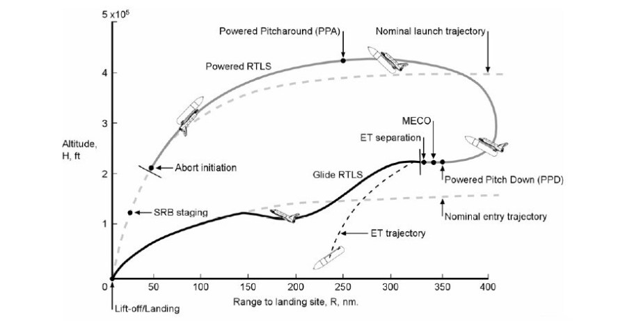
The RTLS isn’t quite so easy to rationalize. While this abort shares the eastbound powered ascent, most of the descent phase would have been westbound. Tying those two events together was an element that was unique to RTLS and a boon to Rolaids sales among the astronaut corps: the Powered Pitch Around (PPA). In a move that only Burt Reynolds could love, the shuttle would have swapped ends while still heading spaceward (at about Mach 5) and never easing off of the throttle. With the SSMEs now facing forward, their retrograde thrust would slow the orbiter’s eastward progress. Eventually, the shuttle would stop in midair (albeit very thin, high-altitude air) and begin heading westward back to the runway at KSC.
The PPA would have begun at an altitude somewhere around 400,000 feet, where there is insufficient air to cause much concern about the aerodynamic effects of tumbling the shuttle. The topic of debate was whether a handicapped propulsion system would have sufficient control authority to whip the orbiter/ET combination around at the 10-degrees per second rate required for the PPA. Many experts agree that a healthy orbiter could pull it off…but healthy orbiters don’t do RTLS.
There were two camps regarding the pitfalls of the shuttle doing Mach 5 in reverse with the SSMEs blazing. Some thought that this was like spitting into the wind, and the shuttle would be negatively affected as it flew through the plume of its own exhaust gasses. Others believed that the RTLS retrograde burn was no different than the deorbit retrograde OMS burn that began the entry phase of every shuttle flight.
A further concern with the PPA was the rate at which the shuttle/ET would descend. As the shuttle’s eastward progress began to slow after the PPA, it would begin losing altitude at an ever increasing rate. At the point where its eastward velocity was zero and it began to accelerate westward, it would have been falling vertically at greater than Mach 1! Mind = blown.
Such a fast descent rate would have subjected the orbiter and ET to significant and ever-increasing dynamic pressure and heat loading. The descent rate would have been gradually arrested as the shuttle picked up westbound velocity (about 200,000 feet of altitude is lost during the PPA), but the air would get thicker and cause more friction with each foot of altitude lost. Whether the vehicle could have survived this torture is yet another RTLS-related point of discussion around NASA water coolers.
For the sake of argument, let’s say that all aspects of the PPA went perfectly and the shuttle was zooming back towards KSC (called the “flyback phase”). Rather than breathing easy, the crew would have to negotiate what many consider to be the most difficult and risky portion of an RTLS: the Powered Pitch Down (PPD). With the SSMEs still burning, but the ET nearly empty, the shuttle would be placed in a slight nose-down attitude. This attitude would be held through MECO and the firing of the explosive bolts that jettison the ET (good riddance!). A few bursts of the shuttle’s downward-firing reaction control thrusters would have put elbow room between the orbiter and the freefalling ET.
The point of the PPD was to maximize the shuttle’s odds of making a clean getaway from the jettisoned ET. What made it difficult was the precision and timing with which it had to be executed. Immediately after clearing the ET, the shuttle’s nose would have to be raised to a specific positive angle. This move was necessary to position the belly-mounted heat shields to do their job through reentry. Just like the PPA, the PPD was not really a question of piloting skill (most of the maneuver could be flown by auto pilot), but whether the damage already absorbed by the shuttle would allow it to perform these precise and critical maneuvers.
But It Works In the Simulator
While the success rate for simulated RTLS scenarios wasn’t perfect, it was good enough to provide reasonable assurance that the energy aspect of the equation could be managed by the onboard computers and savvy pilots.
Despite any misgivings anyone may have had about RTLS, it was the only option when faced with a problem early in a launch. As such, the RTLS was practiced religiously by every flight crew in the Shuttle Mission Simulators (SMS) at Johnson Space Center (JSC). The same mission-specific data that was loaded onto the shuttle’s General Purpose Computers (GPCs, which provided guidance through aborts, among other things) was also loaded onto the SMS platforms. This meant that each simulated RTLS was a little different depending on the specifics of that mission, such as the payload mass, launch azimuth, specific SSME performance, etc.
Luis Betancourt was a JSC engineer responsible for validating the performance of these software loads in the SMS. Part of the testing protocol required Luis to sit in the commander’s seat and “fly” the simulator through RTLS scenarios. With all of that experience in the left seat, he picked up a few tricks. Luis notes, “It was all about energy management. For the most part, we had success if we knew how to manage our energy.”
Presumably, the shuttle pilots and commanders knew all those energy management tricks as well. While the success rate for simulated RTLS scenarios was not perfect, it was good enough to provide reasonable assurance that the energy aspect of the equation could be managed by the GPCs and savvy pilots. The only lingering question is whether the SMS adequately factored in all of the risks associated with a real RTLS.
Dress Rehearsal
Early in the Shuttle Program, NASA management felt that an intentional RTLS was a necessary first step in proving the validity of the shuttle concept. In fact, STS-1 was planned as an RTLS flight. Commander Young dissented rather poetically, “Let’s not practice Russian roulette, because you may have a loaded gun there.”
Mr. Young’s opinion certainly carried much weight. We’re not talking about some risk-averse, desk jockey statistician. This is a man who made peace with the risks of travelling to, and walking on the moon. Yet, he found RTLS a bit too much for his taste. It’s a little like Spinal Tap telling you to turn your music down! “Turn it down” is exactly what the NASA planners did. While STS-1 was not without its difficulties, it did not include an RTLS.
The debate over whether RTLS was a valid abort scenario is not likely to end anytime soon. Now matter how you label the participants (optimists and fatalists, adventurists and pragmatists, Rosary kissers and number crunchers) it seems they all stand near the fence. This is one argument where rarely does one side have difficulty in sympathizing with the point of the other side. Whichever way a genuine RTLS would have ended, it would have been a near thing. For that reason, I think that there is one point that both sides of the RTLS debate will always agree on: we are better off not knowing the real answer.
Terry Dunn worked for 15 years as a NASA contractor at NASA Johnson Space Center, and now lives in Lubbock, Texas, where he works as an engineer in the plastics industry.
Photos courtesy NASA
Premium: Testing Airbag Detonation in Norm’s Backyard
Go behind-the-scenes of our most recent video and watch us set up the high-speed camera test of an airbag being detonated on command. We had no idea what could happen while we were recording this, so you can see that we’re a little bit nervous. Especially Joey.
Episode 199c – Recorded Before We Knew Whats App – 2/20/2014

This week, Will, Norm, and Jeremy Williams discuss the latest Apple rumors, Nvidia’s new Maxwell architecture, the Comcast/Time-Warner merger, and router security. All that, plus what we’ve been testing, an update on Jeremy’s Kickstarter project, and a whole lot more. Enjoy!
Bits to Atoms: Your 3D Printing Software Options
When you first get a 3D printer, the immediate reaction is to print something awesome. But if you don’t have a lot of experience with 3D modeling, where are you going to find the files to print? Fortunately, there is a massive amount of free 3D models that you can download and print at home, in repositories like Thingiverse. And in fact, MakerBot and others have already dipped their toes into selling models to download and print in their own marketplaces.
But there’s something extremely satisfying about printing a creation of your own design. Unfortunately, 3D modeling has traditionally required expensive and intimidating software that requires a relatively steep learning curve. It’s not as easy as LEGO. The good news is that with the 3D printing boom there are suddenly a lot more accessible options and most of them are free! There is still a lot of learning to do so let’s get you started down the path.

There are quite a few software choices available to create your own 3D models, the trick is finding the one that works for you. When it comes to creating three-dimensional objects digitally there are two main choices: CAD and polygon modelers.
CAD Modelers
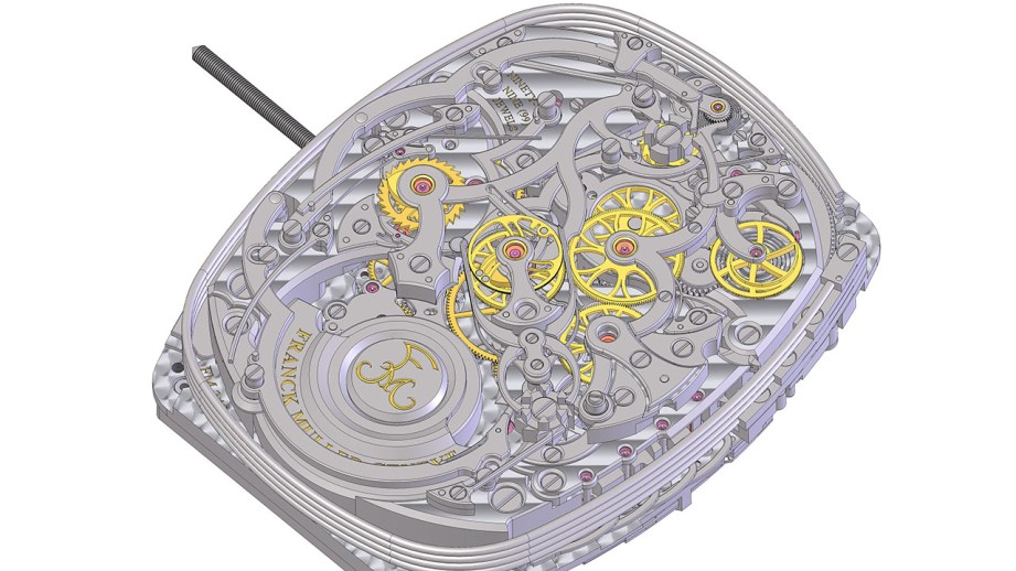
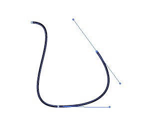
Computer-Aided Design (CAD) is typically used for mechanical design where precision is needed. CAD models are ‘solid’ and represent an actual volume in space whereas polygon models are not truly ‘solid’ as demonstrated in my MintyBoost video. CAD programs model with NURBS (Non-Uniform Rational B-Splines) which describe the object using splines (curves) that have control handles for adjustment.
Think of using the pen tool in Adobe Illustrator to make Bézier curves and using the handles to adjust the curve. NURBS work a lot like this and can be modified quickly and easily and lend themselves to smooth, organic shapes.
Since the splines that describe a NURBS surface are mathematical functions, CAD models are parametric, meaning you can make a panel, define the thickness as 10mm and it would retain that characteristic even if you doubled the overall size. CAD interfaces are built to accommodate precision and provide constant measurement feedback, tools for designing machinery and even the ability to assign and simulate materials and mechanical function in some packages.
Polygon Modelers
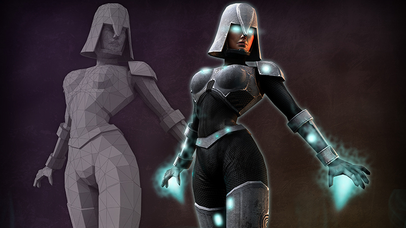
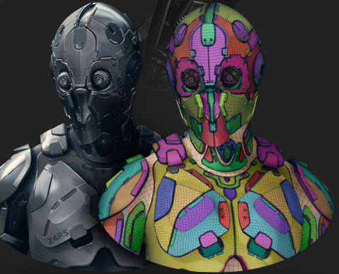
Polygon modeling is generally used in the entertainment industry for visual effects, animation and games. Models are pretty straightforward, consisting of points in space, connected to each other by edges which form polygons that make up the model. Animation and games use a tremendous amount of geometry so the idea is to build your assets using as few polygons as possible. A lot of tricks are then used when rendering (computing the final image) to make models look like they are more complex than they really are. This takes a lot of computing power but far less than a really complicated model with a high poly count.
NURBS can still be used in poly programs but require a lot more computing power and aren’t used as much any more. If NURBS are used the model is usually converted to polygons when finished. Since the goal is low-poly models and cheats are needed, polygon modelers typically have more advanced texture and animation features than CAD programs.
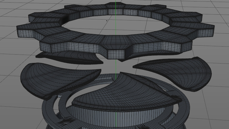
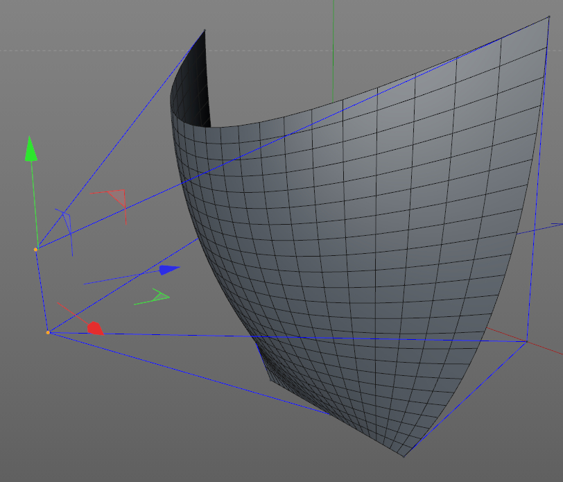
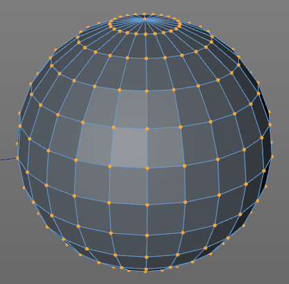
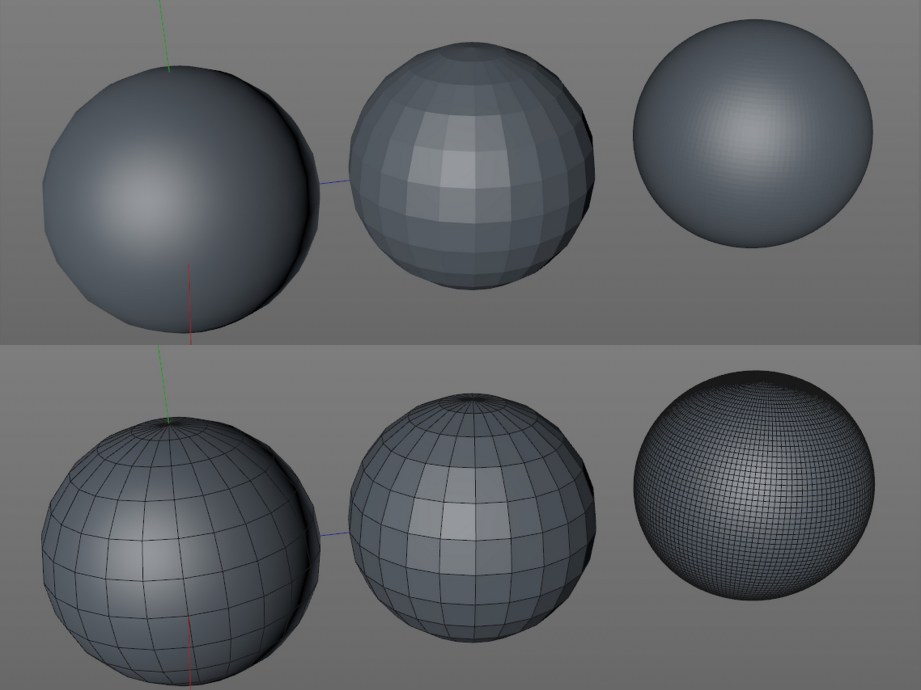
Having said all this, when using a polygon modeler for 3D printing you may throw all that out the window and model with lots of polygons. Why you ask? 3D printers only print pure geometry, they can’t use algorithms to cheat and make models look smoother or more complicated than they really are. So if you want a sphere to look like a sphere, it has to have enough polygons to print smoothly.
To make things even more confusing, many polygon modelers have shaders built in that automatically make models look smoother and you need to make sure to turn them off for 3D printing models, so what you see is what you get. Otherwise a model that looks perfect in the program may turn out all blocky when printed.
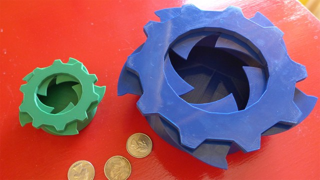
So why even bother using polygon modelers for 3D printing? In the end it depends on what you want to build. If you don’t need high precision and just want to build something that looks visually appealing polygon modelers work fine. They may be more approachable than a CAD program and some objects can be easier to build with a poly modeler. Everything I have built including the Octopod was done in a poly program and turned out great. I have recently started to learn CAD so I can use whatever the right tool for the job is.
Sculpting Programs
Sculpting programs are a third option which are great for both accomplished artists and beginners. Most sculpting programs are technically polygon modelers but are optimized to handle really high poly count models which make them perfect for 3D printing. Action figures, collectibles and game characters (ie: anything Norm buys) are often created with sculpting programs. Generally you start with a virtual ball of clay and use virtual carving tools to form your model. I find that sculpting programs work well for those who just don’t get polygon and CAD programs.
Hardware for Modeling
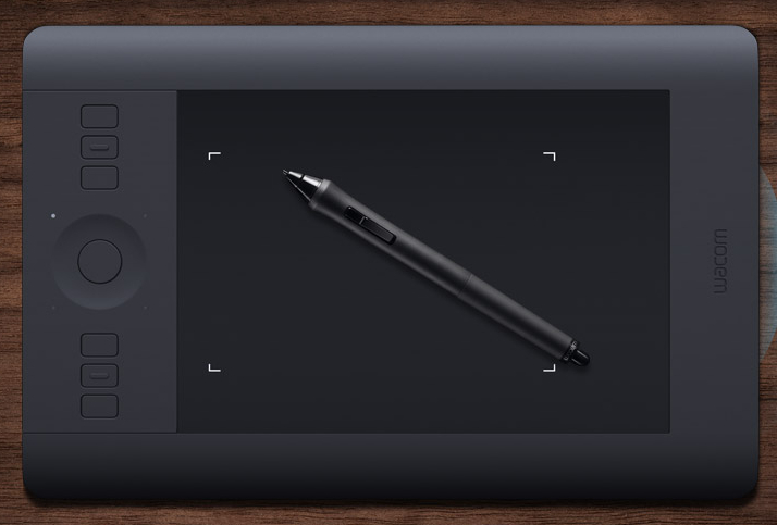
Ok, I’m going to say this right off the bat: use a mouse! Most people I know only use a laptop anymore and trying to use a trackpad for a modeling program that traditionally uses a 3 button mouse is an exercise in frustration. To be even more picky and weird, pay attention to the middle mouse button. It gets used a lot in modeling programs and I have found some mice have an extremely stiff middle button that causes fatigue. I have a Logitech M505 (discontinued) for my laptop and a G600 for my desktop but my all-time favorite was the Logitech MX518 which is sadly discontinued as well. If you are going the sculpting route you can use a mouse but I would suggest a graphics tablet such as a Wacom to take full advantage of the interface.
Most of the free programs listed here should run fine on any decent laptop (ie: not a netbook) with at least 4GB of memory (8GB recommended). If you step up to higher-end programs a dedicated graphics card is recommended. I’m in the market for a new laptop and would love to get an Ultrabook but many use the dreaded integrated graphics card. The good news is it sounds like the newest generation of Intel HD graphics are capable of running 3D stuff relatively well. We shall see.
STL Files
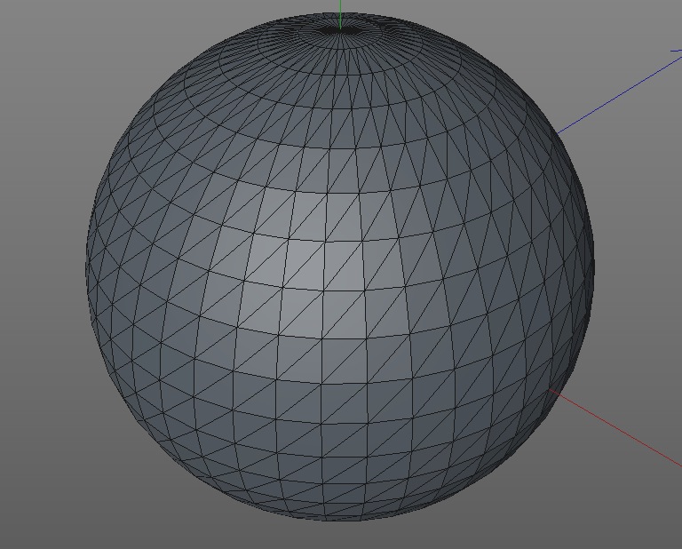
Regardless of how your model is built, ultimately it needs to end up as an STL (stereolithography) file that describes the surface using triangles. This is similar to how polygon models work except they are usually built using quad geometry (see spheres above). Machines deal with triangular geometry better and only need to know what the surface looks like. Many programs will output an STL file or may need a plugin to do so, they are marked on the software chart below. For those that don’t output STL, your best bet is to output as an OBJ file and use netfabb to both repair your mesh and convert to STL. We’ll cover this more in a later column.
My Software Picks
There are almost too many software packages to choose from and I am by no means an expert on all of them but here are some recommendations to get you started. My quick picks, all free, are Autodesk 123D Design for CAD, SketchUp Make for polygon and Sculptris for sculpting.
123D Design has some nice tools for precision, it’s easy to use and has versions for every platform. This is just one program in the Autodesk 123D line all of which are free. If you are a student, you can get everything Autodesk makes including 3ds Max and Maya for free!
SketchUp Make (used to be just SketchUp) was owned by Google until recently and is also easy to use. You will need one of the indicated plugins to export STLs. While I like SketchUp it can sometimes output models that are unprintable due to geometry problems which can usually be fixed by running through netfabb.
Sculptris is a great program from the makers of ZBrush, an industry standard for digital sculpting. You will need to output as an OBJ and use netfabb to covert to STL.
As far as the other picks, Tinkercad is a very cool web-based app recently bought by Autodesk. OpenSCAD is ‘CAD for programmers’ and you basically build models by typing in all the parameters.
SolidWorks and Inventor are two industry standards for CAD. Blender is a great open-source polygon modeler with a large community, learning curve is steeper than others. 3ds Max, Maya and Cinema 4D are high-end, industry standards but worth learning if you are serious about modeling. 123D Sculpt and Creature are both iPad sculpting apps but Creature also allows you to insert a skeleton for posing your creation. ZBrush is an amazing sculpting program that can wrangle millions of polygons; an industry standard.
Learning Modeling for 3D Printing
In addition to all the free software, there’s also a ton of free ways to learn. The first place I would start is the manufacturer’s user forums. Just about all companies have them and their reps are on there daily so you can get it straight from the source. YouTube is of course a good place to go but for all the good tutorials, there are double the amount of bad ones to wade through. The CGSociety is both a great resource for all things polygon and guaranteed to make you feel like crap about the things you make. I’m kidding of course, but the level of talent displayed here makes me feel like I know nothing. Creative Cow is more of a general entertainment production site but it does have a lot of 3D stuff as well. As a Cinema 4D user I should also give a shout out to my favorite place to go, Cinema 4D Cafe which has excellent free tutorials.
Sometimes you just want to get it done and paying for it is worth it. The Gnomon Workshop is pretty great and has some freebies. Digital-Tutors and Lynda.com are worth checking out as well. I will also recommend the book, Digital Modeling by William Vaughan (yes, a book!) which has very good non-software-specific polygon modeling instruction. It has a heavy lean toward entertainment production but the modeling info is very good and he touches briefly on 3D printing.
I realized that most of my recommendations are all for polygon modeling, but it’s what I know. If I find some good CAD sources I will post them in the comments.
So that’s it! It’s going to be frustrating at first, but try some simple stuff and stick with it. Building and printing your own stuff takes 3D printing to another level and the satisfaction of displaying something you built is worth it.
Photos courtesy Sean Charlesworth unless indicated.
Premium: Adam Reacts to the Zero Theorem Trailer
Adam, a huge Terry Gilliam fan (don’t worry, we’re still doing the Totally Unauthorized Commentary for Brazil), watches the trailer for Gilliam’s upcoming movie The Zero Theorem. Here is his unbridled reaction and thoughts on the trailer.
The Zoidberg Project, Part 8: Rethinking the Claws and Feet

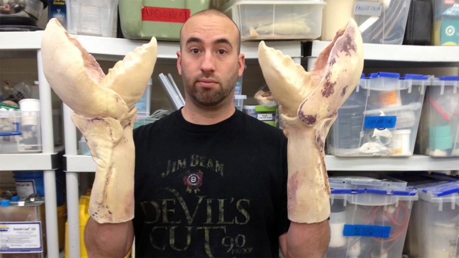
Pulling a rigid cast from a rigid mold can sometimes be tricky. In the case of Zoidberg’s claws, I had a major change of direction in how I wanted to build them. If you remember, I originally sculpted and molded the claw with the intention of pulling a latex and soft polyfoam casting, but the casting was was too tight–it was slightly uncomfortable to move in and got hot very fast. Luckily, I made the mold in such a way that it was still possible to pull a rigid part without breaking the mold for an undercut or locked detail.
When you pull a soft part (latex, silicone, or other flexible material) out of a hard mold (plaster, epoxy, or other rigid material), the flexible part will bend and flex out of small details and areas that might lock together like a puzzle piece. So, to pull a rigid part from the same rigid mold can be a little complicated.
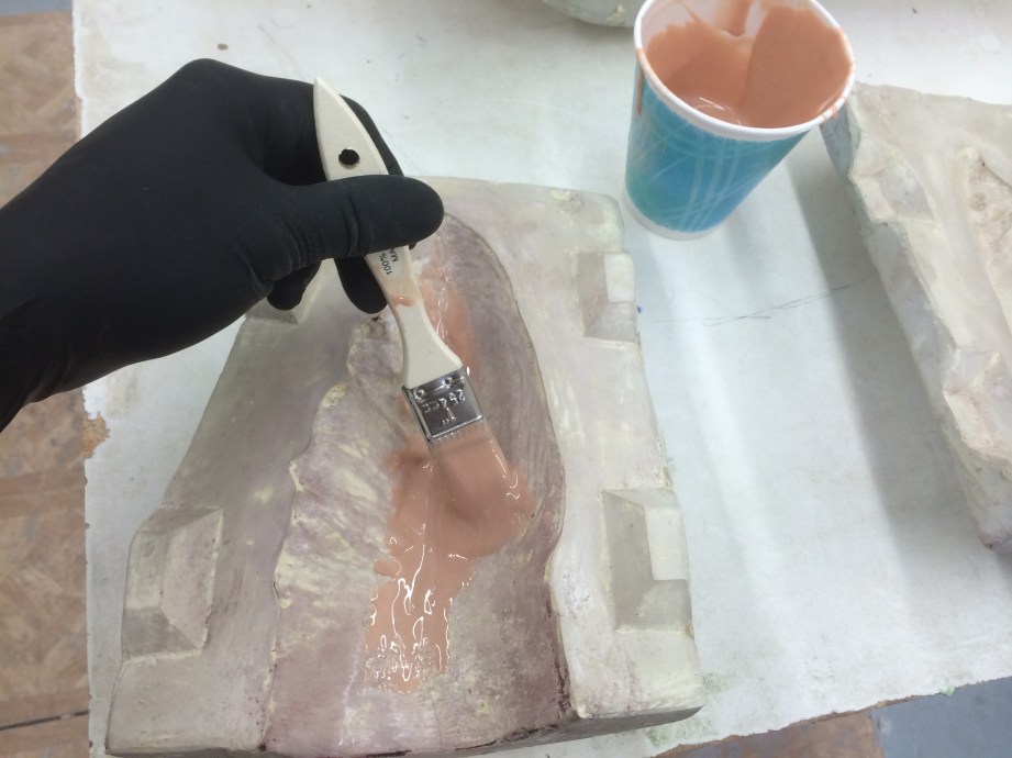
The first step is to properly release the mold (separating it from the cast part). Using a proper release agent in the mold will eliminate one of the things that might make my part stick to the plaster mold. In this case, I’m going to use two coats of wax. This happens to be the wax that is in my cabinet at the shop, but any carnauba wax (eg. car wax) will do. Once one coat is brushed in and the solvent in the wax has evaporated, I apply another coat. These coats have to be put on thinly, as not to clog up any of the details or build up residue. Then, right before I start the plastic step, I’ll spray a heavy coat of Ease Release 200 in for extra protection.
The Smooth-On surface coat I usually use comes in either grey or a heavily pigmented red-oxide, but I don’t want that for Zoidberg’s claws. There are also white and black surface coats available from other manufacturers, but again, that doesn’t help me. I want the surface coat to be a color that can easily be painted to the paint scheme that is in my head for Zoidberg. This means I’ll need to get on the phone with my pal Jason over at Smooth-On to see what options I might have. The reason I want a surface coat is that the regular laminating resin has too low of a viscosity and won’t build up a decent thickness in one or two coats. Surface coats usually have thixotropic (thinning) agents and fillers that make them more durable as well.
I remember back a few weeks ago, I was playing around with some worbla thermoplastic and trying to get a sandable surface, and Jason recommended using a coating product called Epsilon. It’s a thixotropic translucent epoxy that is the exact sort of material that might work for coating the claws. And as it turns out, Smooth-On has Epsilon in the pigment that will work for this project! I want the base coat for Zoidberg to be a sort of salmon color so that I can layer on different reds to give depth to the paint job. So I add a little of Smooth-On’s So-Strong urethane pigments until it’s just right. Now, I have a surface coat to match exactly the color I want, with a little translucency, and it has about the same setting time as EpoxAcote! This opens a ton of possibilities for future epoxy casts that I might want to make!
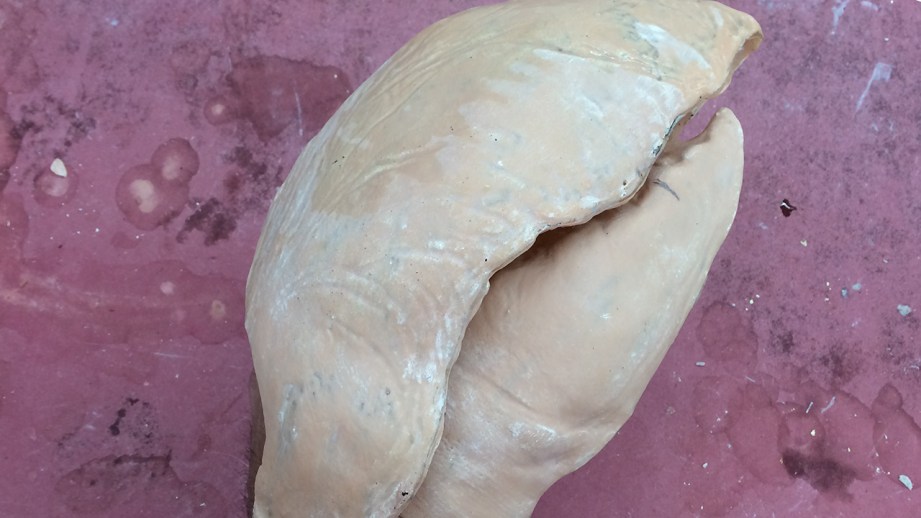
Once this first layer of Epsilon is just about set (when I touch it with a gloved hand, I can leave a fingerprint but none sticks to my finger), I can add a little reinforcement. Because this part doesn’t need to be super structural, I only put in one layer of glass cloth. With the trusty EpoxAmite 102 epoxy laminating resin, I wet out the surface then lightly saturate in some pieces of glass cloth. I want to close the molds and not have to assemble the halves (or thirds) later, so the easiest way to do this is with a little chopped up glass cloth. I basically just chop up a few pieces of the glass until it’s just small strands. This, mixed with a little of the laminating resin will make a super-strong and manipulable bonding material. You just spread a bit of this material along the edges of the part, overlapping onto the flange of the mold a bit. Then, when the mold is closed up, the sides will press together and bond once set.
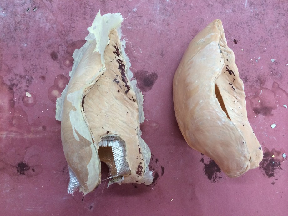
Any little rough or pointy parts can be cleaned up with a dremel after the part is demolded. Because this glass is chopped up so fine here, the little bit of material on the flange is squished between the mold parts, and only produces a super thin part line that can easily be dremeled off. After the molds sit overnight I pop them open and trim them to be Zoidbergs claws! Now I’ll have to fabricate his wrists and the flexible parts to bridge the rigid claws together.
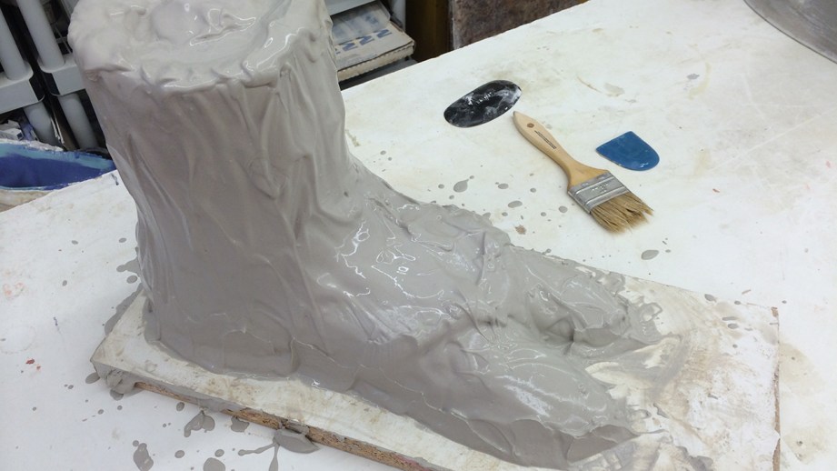
During this process, I started thinking about how I wanted to make the feet differently, too. A while back, I started sculpting Zoidberg’s feet from Monster Clay, and then set it aside. After thinking about how I want to mold and cast each foot, I decided to resculpt the foot out of WED clay. This is partially because it’s faster to sculpt with and partially because it will be easier to clean out of the mold the way i want to cast it. So I had my friend Carson Sciarrino use my roughed in foot sculpture as a guide to block out the new foot, and when I was done with the claws, I jumped back over and finished the foot. It just needs to be a simple shape–not a ton of thought or detail really needs to go into this part since it won’t be seen as much.
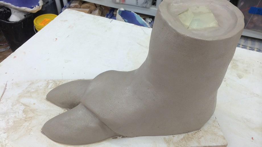
On the top of the ankle I placed a pre-made resin trapezoid key that I keep laying around to easily register the core that I’ll eventually make for this mold. I want these feet parts to be a one-piece mold made out of Ultracal. Ultracal is the same plaster that I used to mold Zoidberg’s claws, and will be perfect for this. Just like when I molded the claws, I seal the sculpture with a few coats of Crystal Clear, then a coat of dulling spray–both from Krylon. Ultracal molds are pretty straightforward–a surface coat, then four or five layers of burlap soaked in more Ultracal. I let it sit for a few hours and clean out all of the clay with a wooden tool. You don’t want to use any metal tools or anything sharp when cleaning out an Ultracal mold, because you can scratch the surface of the mold. Core, casting, and sandal-making to come in another article, after I fab the claws all together.
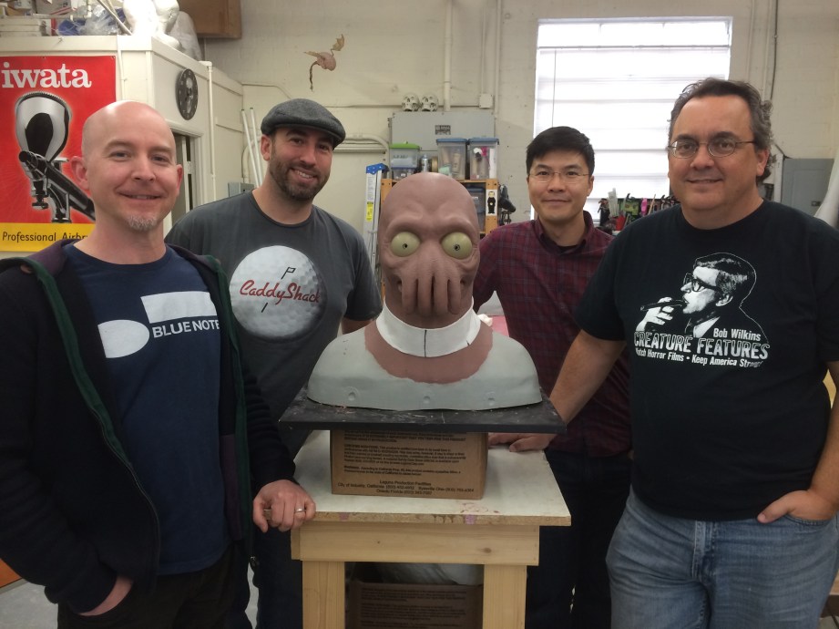
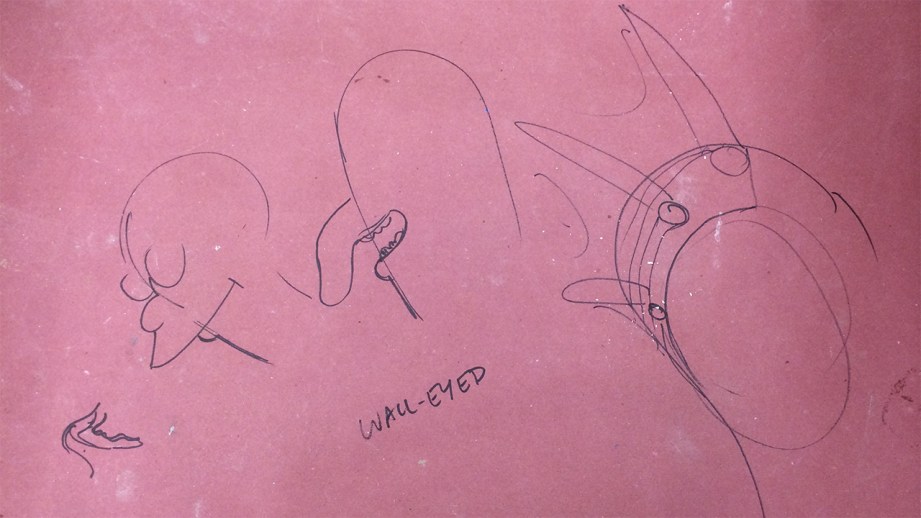
One other thing that happened this week is that some of the directors from Futurama stopped by to see the Zoidberg project! This included supervising director Peter Avanzino, Dwayne Carey-Hill, and Edmund Fong (both also directors on the show). It was great to hear from them say that I’m on the right track in capturing the essence of Zoidberg in their opinion, and they even gave me some design notes which I’m going to incorporate into the sculpture. No major changes, but I’ll be smoothing out his lower lip and removing his chin (in the Groening cartoon world, no one has a chin). Peter also explained to me that Zoidberg should be slightly wall-eyed (not cross-eyed) and his pupil should be about 7/16 at this scale. It’s great to get this kind of feedback directly from some of the people who were responsible for bringing his character to life!
Thanks to Iwata-Medea and Smooth-On for providing materials and sponsoring this project.
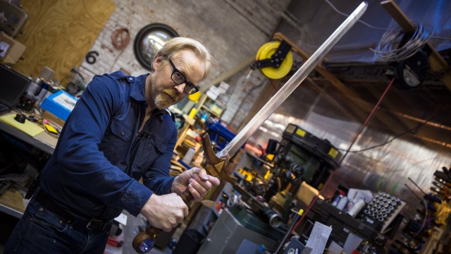
One Day Builds: Customizing Adam’s Hero Sword
Adam and Norm spend the afternoon geeking out over awesome wooden swords bought at last year’s Dragon*Con and then decide to make some modifications to personalize them. This gives Adam a chance to talk about some of his favorite prop-making tools and tricks. Find out how to get your own Hero Sword here.