


You’ve been asking for it, so here it finally is: Adam Savage’s everyday carry. Find out what devices and tools Adam can’t leave home without, and why the items in his pockets might surprise you.
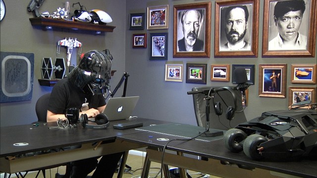
Episode 163 – Vader Helmet – 3/28/2013
The Volpin Project, Part 6: Details, Accents, Refinement, and Mockups
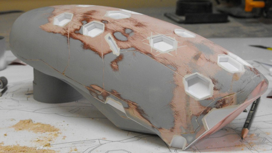
Most of the basic shapes of the Halo Needler have been rounded out (and for those keeping track, I still haven’t started sculpting the actual needles!) so it’s time to begin adding the details that will transform these from amorphous gray blobs into recognizable Needler components. In the last update I spent a fair bit of time discussing the panel lines and recesses on the top casing, so let’s start there.
All those little hexagons would be a pain to sculpt out symmetrically, not to mention smooth sided and with nice right angle edges. In the past I’ve tackled things like this by making a small styrene box and recessing it into the part, then blending the edges flush. Hexagons are more complex than rectangles though, so I came up with a different solution.
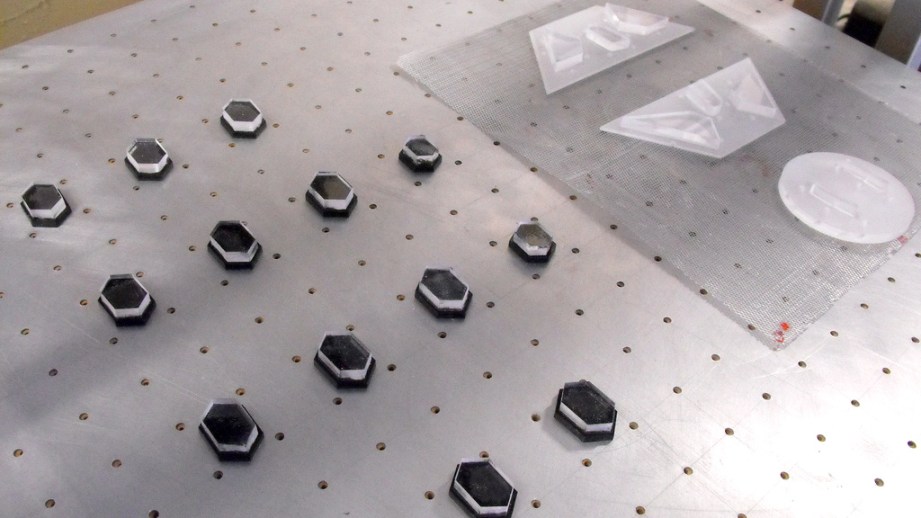
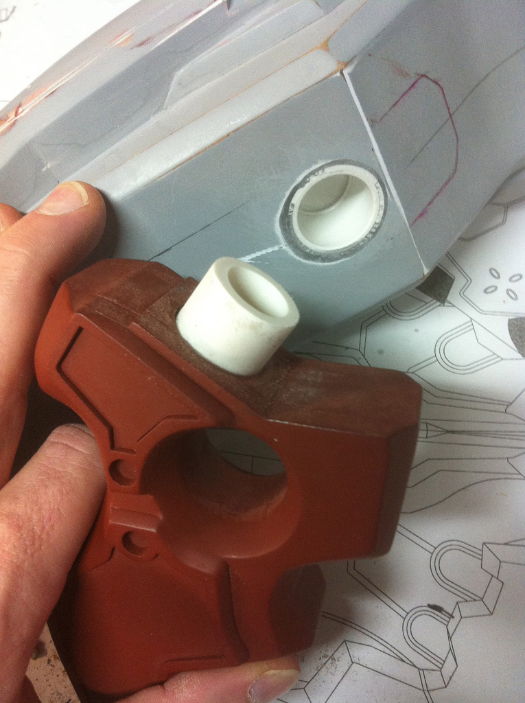
All those little chiclets are pieces of acrylic superglued together. These are the reverse of the hexagons that need to be recessed into the needler body. By vacuum-forming over them then popping them out of the resulting plastic, I got the exact shape I needed for all the hexagonal divots. Even better, they’re all identical since the parts were trimmed out with my laser cutter! That wasn’t a necessity, but it does lend a lot to the aesthetic and helps the resulting forms look more “machined”.
This process was also repeated for a few other recessed parts on the upper casing. But recessing these into the sculpt of the casing was a bit more of a pain than I’d anticipated.
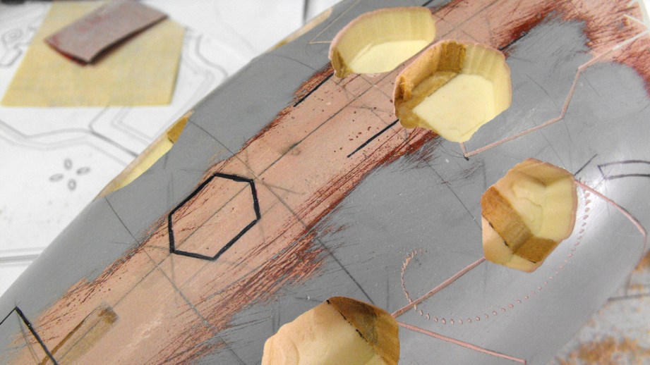
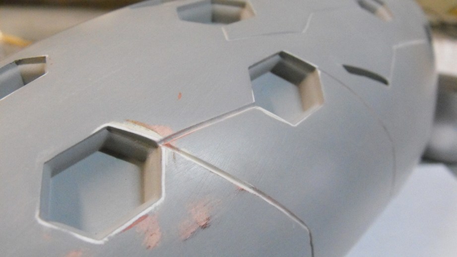
Since the casing is a mixture of bondo, foam and MDF, there are all sorts of density variations I had to deal with when trying to remove material for the divots/cups. I used a dremel tool with a routing attachment to get a uniform depth, but even still it was difficult to control the areas around the MDF and not trim away too much material. In the shot above you can see where the bit got away from me once and went skipping across the surface of the part.
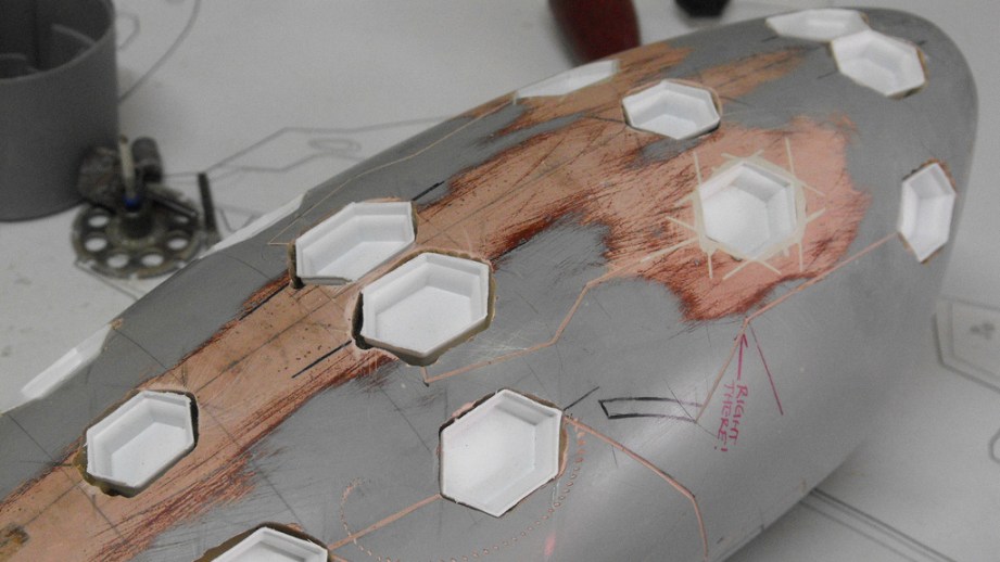
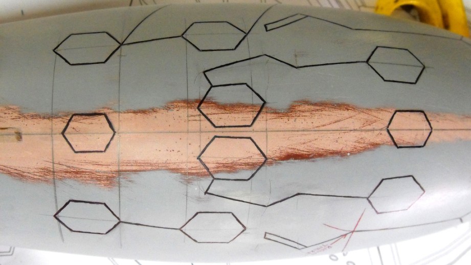
The styrene cups were then superglued into place, and their edges were sanded flush. Since the holes I trimmed were a little oversized, I marked intersecting lines and reference points for where the hexagons should sit in order to glue them into the proper place. You can see there’s a line extending from the front and back of each hexagon recess–this allows me to register the styrene part along that axis and make sure it sits in the proper location.
The gaps in my sloppy cutouts were filled with a type of body filler I like to use for smaller details called “Dolphin Glaze” (made by U-POL) then the whole thing was sanded smooth.
The lines in the part above were all carved out with a combination of a few tools. Initial passes on panel lines are made with a flexible ruler and an exacto blade, then followed up with a series of files to make a deeper channel.
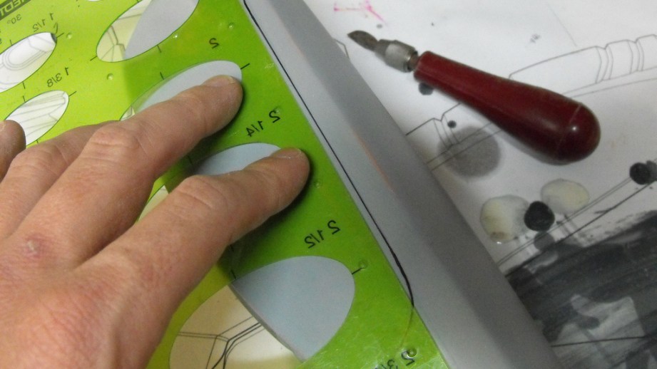
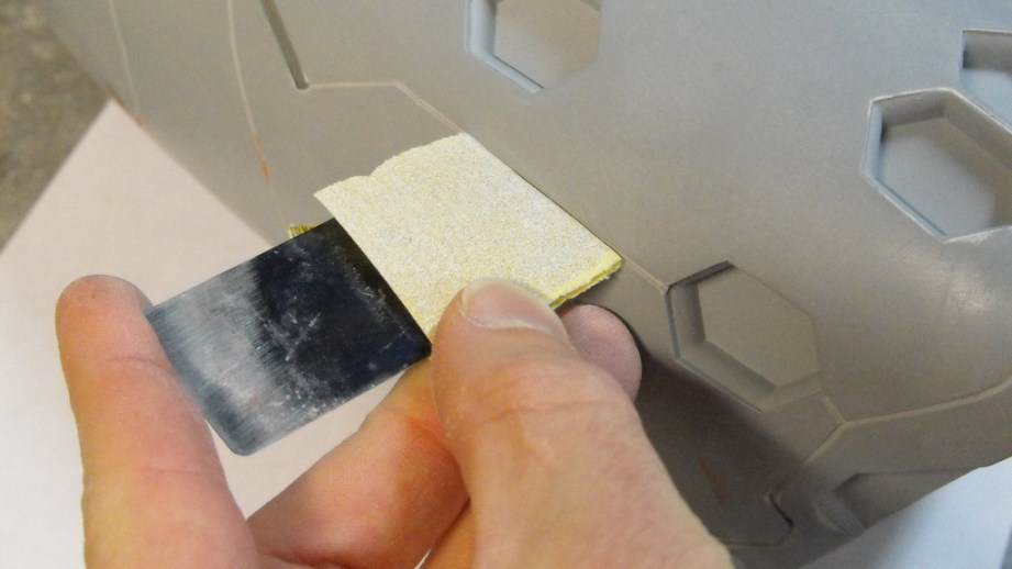
For curved sections, I use an engraving tool typically used on lino block carvings. In order to make all the panel lines a uniform thickness and depth, my preferred method is to wrap a piece of thin gauge stainless steel in some 220 grit sandpaper, then follow the path of the lines trimmed by the engraving tool. This will even out any choppy sections and make the finished results look smooth and machined. You can use a needle file on some sections as well, though for this project I found them to be a bit too wide.
It takes a while, and some sections I had to do more than once since the bondo depth on the casing varies and I’d punch through to the foam every now and again. If it doesn’t look right, fill it with more putty, wait for it to cure, and start over.
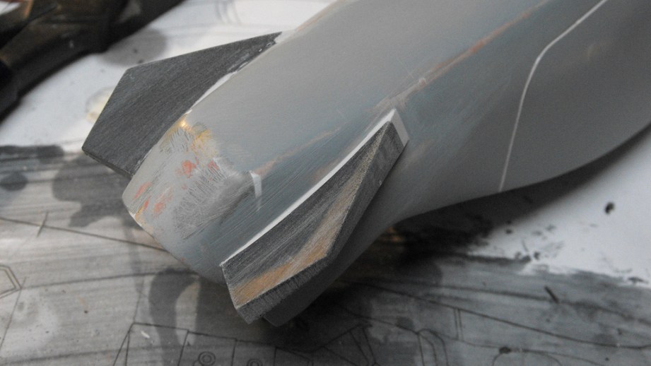
Further refinement also went into how certain parts fit together. I’m not a human 3D printer, no matter how precise I may try to be, and some bits have very complicated edges that need to have a tight seam to the joining part. For instance, the facing edge of the lower “grip” casing:
This needed to mate up to a part that makes up the sort of “barrel” assembly on the front of the gun, and all those complicated edges needed to have a very fine seam tolerance in order to look manufactured. I had the other part sculpted, but certain edges had gaps of ⅛” or more in some places. My friend Bill Doran over at Punished Props has a great name for this technique: The Bondo Squish™
One part is lined with masking tape and waxed, while the joining part is skimmed with a thin coat of bondo. The two parts are squished together, then removed while the bondo is semi-cured but still somewhat flexible.
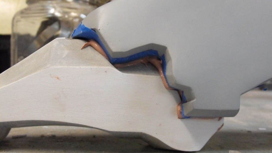
When removed, there’s a fair bit of cleanup to do. Some of this can be removed with an exacto blade while the filler putty is still soft, which is far easier than sanding. There are some voids and cavities that might need filling still, but at the very least this gives a reference as to where the real seam edges should be. A bit of sanding and the seam is much better.
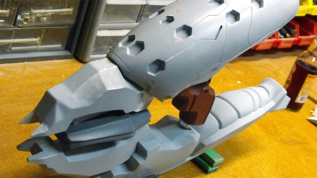
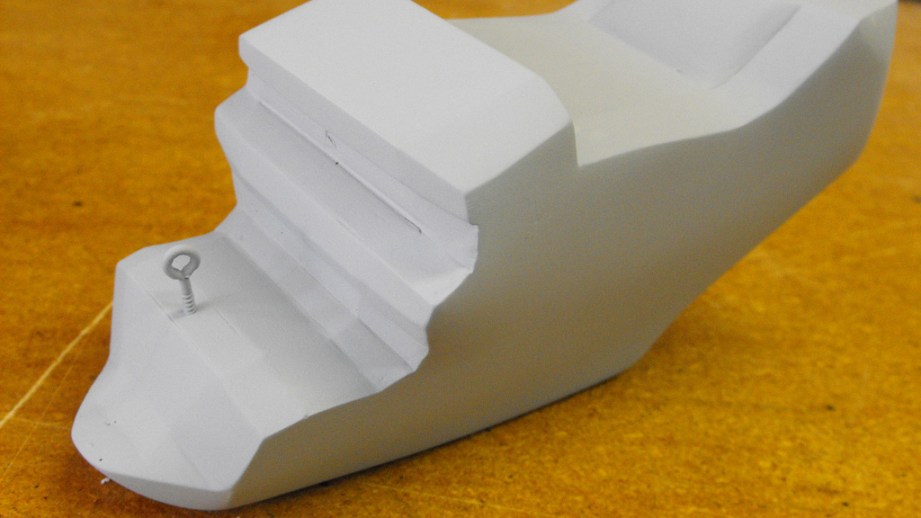
Switching gears again, the lower rear casing is nearing completion. This is possibly the simplest part on the entire project, so it makes sense that it would be wrapped up first. The base frame was completed in my last article, and the next big chunk that needed to be finished was the “padding” which (I suppose) protects the wearer’s forearm when firing. Aliens are supposed to use this thing; I have no idea how that logic works. The padding started out as a styrene cross section to give me a dam to sculpt up to. I used Apoxie Sculpt to get the basic shape down.
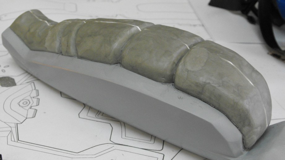
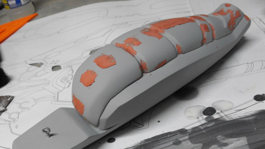
There was a lot of sanding that needed to be done, starting off with 50 grit and moving up to fine grit sponges. A bit of filler putty was used to blend the styrene dam into the rest of the apoxie, as I ran into the same issue I mentioned in the last article about the styrene constantly poking through the other material when the piece was primed.
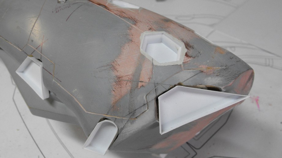
Lastly, I added the little stabilizer fins (seriously, now you designer guys are just screwing with me) to the bottom of the casing. These were trimmed out of ¼” sintra. This stuff is great for quick shaping, but its also pretty fragile and will dent easily if dropped or set down on a sharp edge. These fins will hold up until molding, but typically this would be a bad material choice if you were using these on the finished project.
The third fin isn’t shown here, but it was added later on.
Early on in the first build installment, I talked about taking the wedge-shaped “needle barrel” part and making a mold of it in order to have two identical parts. I’ll cover this in more detail in the moldmaking article to be written later, but this piece got a quick little box mold and I made two resin copies.
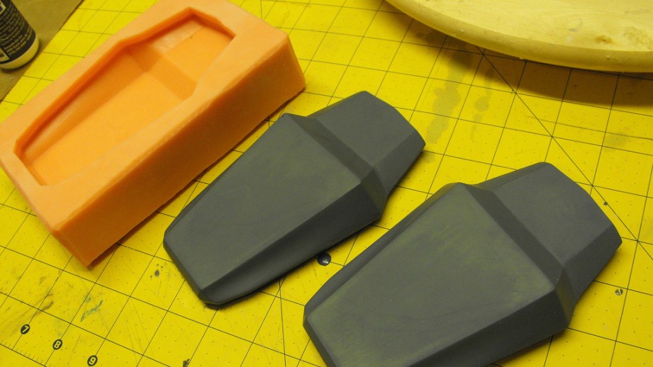
This enabled me to partially put together the whole “barrel assembly” and get a look at how the individual parts fit together. Not bad so far! I’m thinking I’ll make this entire sub-block its own mold so the finished piece can be a sturdy one-part casting which won’t require assembly. The jury is still out on that though.
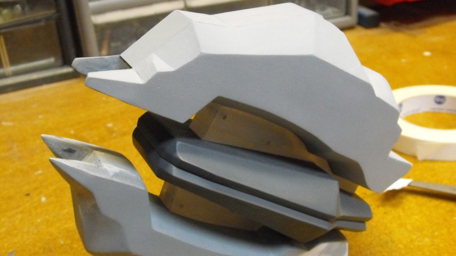
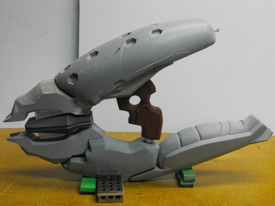
And, of course, I had to plug all the pieces into one another to see how the entire kit was coming together after all this. I’ve installed some little “LEGO plugs” into a few of the master parts–these are sections of ¾” diameter PVC pipe embedded into one piece, with a PVC endcap embedded into the other part. This will make assembly of all the parts much, much easier once the castings are complete. Shown here is the handle and upper casing.
Here’s the whole kit, assembled with some of the plugs inserted, and in a few places, just some double sided masking tape (which is the best thing for mockups like these!) There’s a lot more tiny little details that need to go in places on the upper casing, and even more recesses that need to be carved out of the lower parts as well. There are also two parts I haven’t started on yet, but those will be pretty quickly sorted out before the pieces go into moldmaking in another few weeks.
This is a big gun.
Hope you’re enjoying the process! The next build article will detail a bit more of the last components that need to be constructed, and also start with some block molding. I’ll be out of town for the next two weeks giving some talks about propmaking at a few conventions, and since the TSA won’t take kindly to me bringing a can of spray paint and a gallon of bondo on a plane, the next Needler build article will be slightly delayed while I’m away from my workshop. (Don’t worry, we’ll still have a special Harrison post in two weeks!–Norm)
The Volpin Project, Part 1: Introductions
The Volpin Project, Part 2: References and Blueprinting
The Volpin Project, Part 3: Selecting Materials
The Volpin Project, Part 4: Taking Shapes
The Volpin Project, Part 5: Bondo Strikes Back
Building an Inexpensive Toolkit for Beginners

Still Untitled Supplemental: Adam’s Inexpensive Beginner’s Toolkit

Knowing what tools to purchase when you’re a fledgling maker is tough, especially if you’re on a tight budget. And building a tool collection can get downright pricey–the price swing from a cheap version of a tool to the expensive version can be massive. On the March 26 edition of Still Untitled, Adam, Norm, and I came up with a universal list of tools to put in a cheap toolkit for beginners.
You should really listen to the whole show for context, but the short version is that you shouldn’t be afraid to start out with inexpensive or used tools when you start out. I’ve also broken out the optional, but recommended upgrades or enhancements to the kit. Some of the optional items are only applicable to people who are into electronics or woodworking, while some are simply a bit more expensive than we’d put in a beginner kit.
One last note: we almost certainly forgot something important and obvious, so please post our omissions in the comments below. And please, be nice.
- Big Phillips Screwdriver
- Small Phillips Screwdriver
- Big Slotted Screwdriver
- Small Slotted Screwdriver
- Pliers
- Needle-Nose Pliers
- Wiha Jewelers Screwdrivers
- Claw Hammer
- Rubber Mallet
- Adjustable wire strippers
- Wire Cutters
- Soldering Iron
- Corded Hand Drill With Hand-Adjustable Chuck
- 25-Foot Extension Cord
- Set of Drill Bits (aka a Drill Index)
- Hacksaw
- Jigsaw
- Japanese Handsaw aka Ryoba
- Tape Measure
- Awl
- Digital Calipers/Micrometer
- Pop riveter
- Xacto Knife
- Single Edge Razor Blade
- Nail Files
- Adustable Crescent Wrenches
- Socket Set
- Jeweler’s Tweezers
- Plier Tip Tweezers
- Eyebrow Tweezers
- Allen Wrenches
- Scissors for Everything Else
- Clip Lead
- Multimeter (w/ Continuity Tester)
- Spring Clamps (aka Grip Clips)
- C Clamps
- Electrical Tape
- Duct Tape
- Masking Tape
- Doublestick Carpet Tape
- Foam Doublestick Tape
- Elmer’s White Glue
- Contact Cement
- Cyanoacrylate
- WD-40
- 3-in-1 Oil
- Basic Sewing Kit
- Safety Glasses
Optional Tools and Upgrades
Episode 162 – Oculus Rifting – 3/21/2012

The Oddities Inside Adam Savage’s Home Office
Adam invites us inside his home to share the collection of prop replicas, 3d prints, oddities, and artifacts he keeps in his personal office for inspiration. And yes, that’s the Bride’s sword from Kill Bill.
Scrounging, Buying, Finding Materials – 3/19/2013

Episode 161 – Google Reader is Dead – 3/14/2013
Cooking Perfect Omelettes with Adam Savage (and Traci Des Jardins!)

Adam’s not-so-secret passion is cooking, and his specialty is eggs. We pay a visit to his kitchen to watch Adam prepare his favorite breakfast, and are joined by a surprise guest to discuss the best way to cook an omelette!