Maker Profile: John Findra’s Classic Wrecks

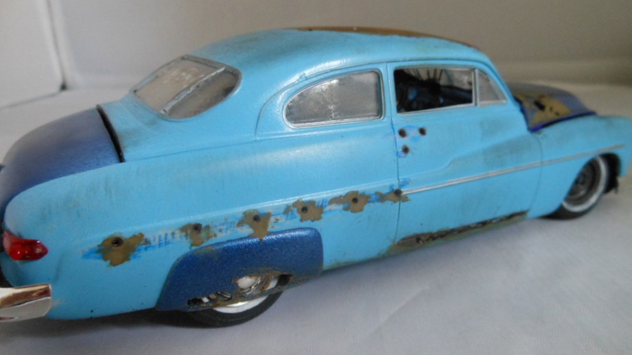
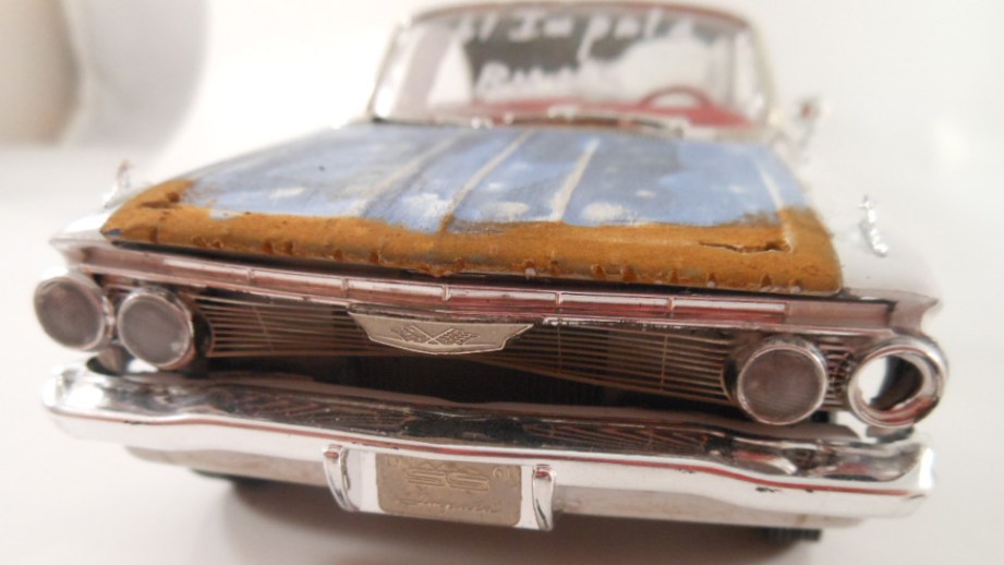
I first heard about John Findra on a Virgin America flight, while watching the BoingBoing channel. An Etsy-produced video featuring Findra drew me to his store, Classic Wrecks, where Findra describes his works as “handmade junker car art”. And while the 1:18 scale model cars he sells may not look out of place in a junkyard, they’re definitely not junk. Findra painstaking transforms new model replicas into aged junker cars with intricate painting, fake rust, and custom plastic. It’s a case of extreme weathering that, unlike props for movies, is made to be appreciated up close and in photographs. I corresponded with John to learn about his process and what stories he’s trying to tell over the thousand or so model cars he’s modified.

What was your background in model building and how did you get started with your Classic Wrecks project?

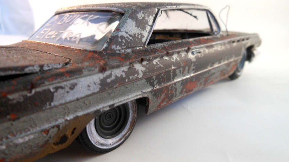
I got started late in the late fifties when I was a kid. In those days there were always car model contests and after I saw some displayed, I asked a friend if I could have on of his rejects. He gave me a beat up ’59 Buick that was a mess and I remade it [like new]. I have been looking for that Buick ever since. After I retired, I started up again [making models]. It took weeks to complete a perfect example, and I was going to throw away some imperfect ones but I decided to try something different. I decided to make it look like a junker.

It didn’t take too much time and the result was so much more realistic and interesting. The patina of the paint alone was more varied and when I added the body rot and put the rust on it created almost a watercolor effect.

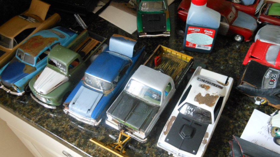
My wife had a shop on Etsy and I put my first two Junkers in her shop and sold them to a customer in England. After that, I was hooked. I started to take all the perfect ones I had made over the years and wrecked them. So when I ran out on those I started to buy the kits from companies such as Revell, AMT, Tamiya, Monogram and others.

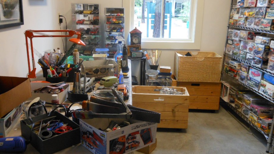
What tools do you use for your model jobs? Are these tools someone could just get at a typical art supply store?

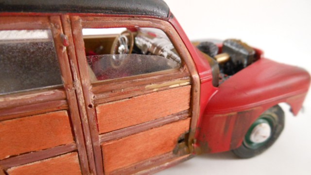
I use a lot of different products to create the look of my Classic Wrecks. I use actual automotive paints, acrylic art paints and ink pens to create the paint schemes. I use art supplies such as rust distressing solutions, fabrics, leather scraps from old wallets, wiring from old electric devices, Indian ink, plastic from plastic bags, small metal rods and tubes, wire mesh, wood planks and thin wood sheets (for woodies, pickups), and other items to create the look I am after.

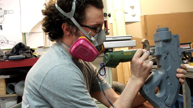
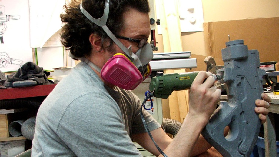
There are many tools in my shop. The major tool is the Dremel and all of the differnet bits and fittings that go along with it. It’s used to create the drilled out headlights, strip off chrome trim and most importantly the actual rusted out body rot.

Several different drill bits are used to create the holes in the body. These bits are in barrel form, rounded form with groves so you can chew up the plastic from the inside of the body to create the jagged pattern. The drill is also used to create the broken window effect by first drilling a hole and using a very small plier to nib the plastic away and create that jagged look. You can also use a small sanding bit that is used to wreck the tires and create the desired patina.

Another important tool is the exact-o knife with a very sharp blade. I use this to stripe away trim chrome detail so I can create a line of holes where the chrome once was attached to the car. When creating a two tone paint job the blade comes in handy to create a line of separation between the two paint colors. I use painters tape and a steady hand to create the perfect separation between the paints, the blade most be perfectly sharp to cut the painters tape in a line and prevent tears in the tape.

Pliers are important to create the wired engines and to hold very small pieces in place for glueing. I go to art stores to buy rusting solution, jewelry chains, tools, paint pens, fabric. foam, wood, wire, decal graphics and any miniature item that I can use that looks in the right scale.

How do you begin with a model and when do you feel that your work is finished?

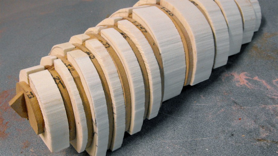
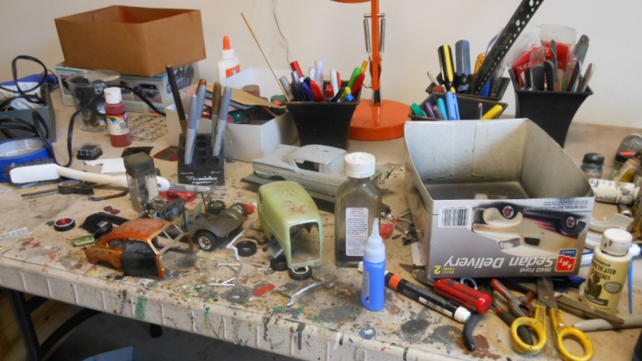
The first thing you need is the car kit. 99% of the the time I use plastic kits because they are much easier to work with to create the body rot and they are more realistic than metal die casts. Metal kits tend to be thicker and not as detailed. Painting is the first order of business. I pay a lot of attention to color combinations to create an attractive color scheme. I have a good selection of automative paints from the auto shop, and usually check the authentic color charts of the actual car I am doing so I don’t select a color that wasn’t available at the time the real car was manufactured. I also have a selection of metallic paints to create a realistic engine compartment and chassis. These include aluminum, steel, titanium, silver gold and copper patinas.

Next, I tear out parts of the model, like the doors or trunk lid, to create a haphazard look of a door that is hanging off or a trunk lid that will not close. I will use the dremel to create the rot holes in the strategic spots that I have observed from reference photos–edges of hoods and trunks, around wheel wells, bottom of doors and undercarriage.

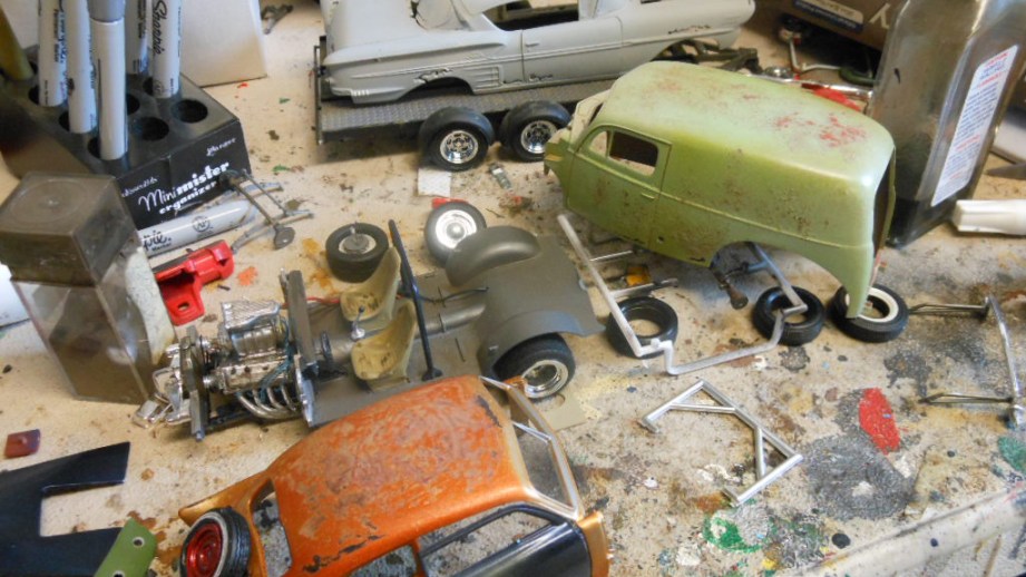
If I decide to do different color panels such as roof, doors or fenders I have to mask off the part being painted to create a perfect demarcation of the painted panel. While these are drying I start the assembly process. You always have to keep moving because the time it takes to complete a model has to be kept at a minimum.

The engine is where I work on next, then moving on to the interior, and finally the chassis until all the sub-assemblies are done. After the paint is dry I need to create the aged patina. This process involves rubbing adhesive dirt onto the finish, sanding, repainting with a slightly different shade of paint, using dull coat to knock down the shine of the new paint, using a exact-o blade to simulate key scratches, using different paint pens to create mud splashes, etc. It’s only done when every piece has been touched and aged and made to look perfectly imperfect!

You’ve mentioned that you want each car to tell a story. Do you approach each piece with a story in mind or does that story reveal itself to you over the course of the project?

There are several ways I approach each project. I get special orders all the time and I get a lot of pictures from my customers. One time, I received over 100 pictures of a car showing every angle. The special orders are great because they are a challenge to get as close as possible to the pictures.

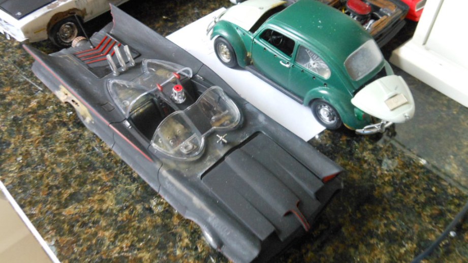
I also remember cars of my past that I recreate. Whether it’s was the blue VW I drove as a drugstore delivery boy, my friend’s Camaro, or some of the cars I remembered parked in my high school parking lot. When I write the copy for the description. I always try to tell the story of that car and the inspiration.

I also sometimes just freestyle and create with no actual car in mind. Here I am tring to tell a color story to appeal to the eye of the viewer. Some of my coolest ones though are of customer requests like the 1966 Ford econoline van that I created from 60’s grainy pictures or the tow truck-wrecked car combo I created from a 1930’s picture.

Photos courtesy John Findra/Classic Wrecks

https://www.youtube.com/watch?v=lfjzpcj6oIk&rel=0&wmode=opaque

One Day Builds: Adam Savage Demonstrates Weathering Tricks

Adam Savage shows us how to paint and weather a newly constructed box to make it look like it’s something that’s been used for decades. In weathering a prop, Adam lets the object reveal its story though dings, scuffs, stickers, and stains. Just wait until you see his secret weathering trick. See detailed photos of Adam’s in-progress and finished box here!

The Volpin Project, Part 4: Taking Shapes

All right! We’ve got our blueprints, references, and a pretty good idea of how to block out some shapes. Its finally time to glue together some foam, plastic and wood and start making a sci-fi glowing needle space gun.

Here’s a standard warning that, while most of us have read it a million times, bears repeating: Whenever you’re working with anything that releases gas, dust, shavings, splinters or particles, wear a respirator! Goggles wouldn’t hurt either if it looks like your material will be shooting particles out violently. I have a dust collector in my shop that’s hooked up to all the tools that spit fine material mist everywhere to help with keeping this crap out of the air. Wear safety equipment like this with everything. Cardboard is technically “non toxic” but you don’t still don’t want to be breathing cardboard dust!

While messing around in Photoshop, I discovered a pretty neat feature in the 3D palette. I have no doubt that people skilled with 3D programs have known about this for ages, but it was a pretty big “aha!” moment for me. In the “3D Scene” menu, you can choose to cross section your model, and even highlight where the cross intersects the part. Words aren’t my forte, so I put together a little animated gif of what this means exactly:

For creating the rear casing, I saved a series of images of the sliced rear section of the gun with the intersecting plane highlighted in red. These were then transferred to Illustrator, and traced into vector format. Since the gun is a series of flat polygons, a little interpretation of the outlines was necessary in order to get a proper curve.

These patterns were transferred onto some ¼” MDF with my laser cutter. Technically you could cut these out completely on a laser, but MDF is a pretty nasty material to go burning holes into, so I decided to just make the patterns here and cut them by hand later on with my scrollsaw.

Finished cut pieces. Also convenient if you’re planning on making a model ship, apparently. I discovered there were a few jumps in the shapes from one step to another, so I cut out a few more inserts to make the curve transition smoother.

The spaces between were filled in with 5lb urethane tooling foam. Since the gaps were variable in width, I had to spend some time slicing different thicknesses of foam to make sure there were as few gaps as possible. Grab a sharpe and label everything – don’t be sqeamish about making notes directly on the piece you’re cutting or sculpting either. A notebook can be misplaced or the correct page forgotten, but if you write “don’t cut this side, idiot” onto your prop, it tends to keep mistakes from happening.

All the sliced sections rough cut and superglued into place. I like to use the really thick “gap filling” cyanoacrylate here, since it will fill the spaces between the foam and the wood well and won’t run down the side of the piece – inevitably gluing your hand to the prop when it does – when you spread it onto the foam.

These blanks were then shaped with some 50-grit sandpaper. Very rough stuff, kind of like sanding with a roofing shingle. A while back my dad stumbled onto some overstock sanding belts at a tool thrift store here in Atlanta, and bought me about 30 belts in 50, 80 and 120 grit. I don’t have a 24″ belt sander, but cutting these belts into squares makes for perfect sanding blocks for rough shaping like this. Sanding belts have a thick fabric-like backing and are generally meant to have a longer lifespan than regular sandpaper. While this isn’t really an option for everyone, it has become my preferred method for doing initial rough passes like this.

This little foam and wood blimp was then skinned with several passes of bondo to even out the shape. If you’re using urethane foam like I am, you can just slap the polyester filler ont here no problem. If you’re using the pink-or-blue extruded polystyrene foam (insulation foam from Home Depot or LOWES) then you’ll need to seal it first with something like acrylic paint to keep the polyester filler from dissolving the foam underneath.

The flat areas on the bottom are a little easier to accomplish. Going back to the blueprints and taking measurements of the lower dimension of the top casing gave me the shapes that were trimmed out of styrene sheet. If you wanted to you could try to sand some bondo into a flat plane to fill in this area, but no sense in making more work when a shortcut will do. The beveled edge sides were also added at this point with some apoxie sculpt.

A whole bunch of sanding later and the base form is finished. From here I can start carving panel lines and indentations into the surface for the hexagonal needle chambers.

Not having any compound curves, the handle for the Needler was wrapped up in pretty short order. The center portion was made from laminated MDF sheets to be .75″ thick – matched to the scaled blueprints printed out before. Additional details on the side were added in .25″ MDF then accented with .118″ acrylic.

The side handles are supposed to have a slight indentation, so an additional insert was cut out of .080″ acrylic and inset into the grip texture. This gives the handle a very slight step, and the process is much easier than trying to trim out a flat plane like this by hand. Once everything was glued up, Apoxie Sculpt was used to fill in the beveled areas.

There’s a fair bit of sanding (you’re going to hear that a lot) between the above shot and this one below, but the handle is about 90% finished at this point. If you’re wondering why it looks like its cast in chocolate, thats the Krylon “Ruddy Brown” primer I’m partial to using. I’ve found it dried well even in the humidity here in GA and doesn’t clump up when sanded. Your mileage may vary, so make sure to test out and find the stuff that works best for you in your climate.

From the descriptions above you can kind of get a sense of how things are going to progress from here. This piece in the art file below is the sort of “barrel” portion where the needles would come out from the in-game model. Since there’s two of these mirrored around one axis on the actual gun, I’ll just be making one and molding it for its twin.

Framework starts out as layers of styrene and acrylic, with profiles drawn from the X, Y and Z perspectives. This gets skinned in layers of styrene for the flat parts and Apoxie Sculpt for the curved bevels. After a lot of sanding, the part is closing in on complete.

Now let’s take that one step further with the “emitter” part – the jaw-shaped piece that affixes to the front of the upper casing. This part has curved sides, but is otherwise a pretty straightforward beveled part. The center spine was cut from MDF parts, with lines etched into the sides for acrylic standoffs.

Disregarding the technicolor assortment of acrylic, these standoffs represent the curve of the outer edge of the emitter. Look at it from a top-down perspective, and I think you can see where I’m going with this.

I used a sheet of .040″ thick styrene to skin the outside of these standoffs – this stuff is very flexible and while it wouldn’t be a good solution for something like the underside of the top casing where we need a nice flat edge, it’s ability to easily form a curve makes it perfect here. This piece isn’t finished just yet – the epoxy clay in the beveled sections need to be shaped and sanded a bit more – but the basic framework is complete. I just need to follow the lines and fill in the geometric shapes of the bevel and its complete.

While this seems like a lot of writing for just a few hunks of primer-tinted shop flotsam, I hope it does a good job of illustrating how I sculpt the basic shapes of a project. I’ll be continuing this trend with the rest of the parts of the gun since I’ve only got about half of it started thus far, and the next project installment will cover adding more detail and depth with panel lines and recessed areas in the base shapes.

See you again in two weeks!

The Volpin Project, Part 1: Introductions

The Volpin Project, Part 2: References and Blueprinting

The Volpin Project, Part 3: Selecting Materials

How To Get Started with Programmable RGB LED Strip Lighting

For more Tested.com content become a premium member, subscribe to our YouTube channel and check out our weekly podcast with Adam Savage!

One of the greatest things about the Maker scene is that there’s just so much of it—it encompasses everything from rocketry to hydroponics. And as a maker, just getting started can be the hardest part: deciding what to work on next, or if you’re new to the scene, what to work on first. So I’m starting up a new series of articles that I hope will help you get your bearings on what’s possible. But I’m going to refrain from calling out specific projects to work on; not only would my list probably be unhelpful (there’s only so many ways to write “build a fighting robot“), it sort of defeats the point of the whole endeavor, which is to express yourself through creating something suitable to your own abilities and interests. Instead, I’m going to look at some cool components that could be a major part of lots of different projects. Hopefully you’ll be inspired.

Today, we’re going to explore the uses of LED strip lighting—a great, simple component that can add a lot of visual impact to any project. LED’s provide bright, colorful and (in some cases) customizable light, and by buying them in strip form you save yourself a lot of time and effort at the soldering bench.

In order to examine the world of flexible lighting, I chose to put together a quick project of my own. I have some problems with the lighting in my living room—particularly when watching movies. With all the overhead lights and lamps turned off, the room gets pitch black, aside from the screen. With any room lights on, glare appears on the TV. So for a simple lighting project, I decided to mount a strip of lights to the back of the screen, to provide a gentle glow for the wall behind it.

Step one was to buy some lights. There are a whole lot of varieties of LED strip lighting on the market right now, but for the most part they fall into three categories, as follows:

Single Color, Non-Addressable: This is your basic “dumb” LED strip lighting. They come in plenty of colors, and are great for providing bright, colorful lighting in fixed location. These are commonly mounted under cabinets or tables to provide a nice recessed glow, or as a source of indirect lighting for home theater setups or display cases. They’re relatively inexpensive, and you can buy them in plenty of colors and intensities.

RGB, Non-Addressable: RGB strips are able to display any RGB color, and can change dynamically. They’re a good alternative for lighting projects where you want to be able to create different moods. They’re more expensive than single-color strips, and require some sort of microcontroller. If you’re so inclined, pre-made kits are available which include everything you need.

RGB, Addressable: The most customizable, most controllable, and just generally most awesome LED strips. Addressable LED strips are color-changing, like the previous category, but go a step further and include a tiny chip in between each and every LED, allowing you to control them all individually. They’re the most expensive, and to get the most out of one you will definitely need a microcontroller. They can be used for the most sophisticated lighting projects, or can even act as an art object all on their own. Additionally, they’re perfect for projects that rely on persistence of vision to create images in the air.

For my project, I decided to go with the RGB addressable strip. “Hold on,” you might be saying, “didn’t you just say that single color strips were good for home theater installations?” Yes, I did, but it’s also important to keep in mind how truly sweet those addressable RGB strips are. I mean, you really should watch the video. I decided on the spot that my TV backlight project is going to have a fiesta mode.

In addition to the lighting itself, I needed a power source. LED strips are powered by direct current sources, and their voltage needs differ from strip to strip—you’ve got to pay close attention to the spec when you buy it, and make sure you’ve got a power source that can provide just the right amount. I decided to go with the addressable strip from Adafruit, which is a very reasonable $29.95 per meter, as well as the power supply I would need to run it. There’s a chance I could have found better prices on individual components by shopping around more, but because I live in Hawaii shipping prices can be a pain, and it’s helpful to get everything from a single retailer.

Finally, there’s the issue of control. You’re not going to get the LEDs to change color by asking them nicely—you need a microcontroller. There are a number of solutions, but the most widely used is Arduino. So I went ahead and tossed an Arduino Uno R3 and its power supply into the cart.

A few days later I got the parts in the mail, and started the process of building my TV backlight. There’s not much to a backlight, of course, but anything involving addressable LEDs takes at least three steps:

First, you have to solder leads to the strip of lights. When you buy LED ribbon, unless you get a whole 5 meter roll at once, you get a piece that’s been cut off of a longer quantity, so they tend to come without leads attached. It’s pretty simple soldering, you just have to make sure that you’re attaching wires to the correct side of the ribbon. Both ends will have a set of four contacts, but on one end the middle two contacts are labeled “DI” and “CI”, and on the other end they are “DO” and “CO”. You want the side with “I”s—they’re short for “In.” The connections are a little vulnerable at this point, so I suggest strengthening and insulating them with a little heat shrink tubing or electrical tape.

Second, you connect the LED strip to the Arduino and the power source. This involves connecting the “DI” and “CI” (data in and clock in) wires to two of the digital pins on the Arduino, and the other two to the power supply and the power supply and Arduino’s common ground. For a more in-depth guide to wiring an addressable LED strip, check out Adafruit’s excellent tutorial.

Finally, you need to use your computer to send a program to the Arduino for it to execute using the LEDs. For this you need the Arduino IDE (which includes the Arduino USB driver), as well as a library that allows you to control the chips on the LED strip. For the particular strip I bought, that library is available here.

I’m not going to go too deeply into how Arduino works or how to use it, because that’s a topic I’ll cover in a future guide. For now, I’ll just mention that you program the Arduino by writing a very simple program in C that defines which LEDs should light up at what time. It’s still programming, so be warned if that makes you squeamish, but controlling the LEDs is about as simple as C programming gets, and you could easily learn everything you need for the task in a few hours.

For my project, I added two push buttons to the Arduino, and wrote a simple program where one button cycles through three modes (steady light, slow “throbbing”, and fiesta mode) and the second button cycles through several different color options. To mount the backlight to the TV, I bought some standard 3M two-sided mounting tape and applied it to the Arduino and the LED strip. I stuck the whole thing to the back of the TV and voila, pleasant mood lighting for any genre of movie and/or fiesta.

Tested Visits the Rancho Obi-Wan Star Wars Memorabilia Museum

We meet Steve Sansweet at Rancho Obi-Wan, a museum dedicated to celebrating the memorabilia and culture of Star Wars fandom. Steve gives us a tour of the incredible museum, sharing the curious stories behind a few of his over 300,000 collectibles. Check out our photos the best pieces here.