


For testing the SteamOS Beta, Will and Norm build two very different PCs to run Linux games and stream games using Steam’s in-home streaming feature. All the memories from the PC Build race come flooding back…will Norm’s PC boot up on its first try?
Bits to Atoms: Making a MintyBoost USB Charger

[Norm’s note: Every other week, 3D printing expert (and Inventern competition champion!) Sean Charlesworth will share some of his insight and experience of 3D design and printing. He started last month discussing modern 3D printing technologies, and will alternate between those guides and walkthroughs of his past print projects to show applications of those tips. Here’s the first project walkthrough.]
I am a huge fan of Adafruit Industries, which was founded right here in NYC by MIT engineer, Limor ‘Ladyada’ Fried and is a supplier of great DIY electronics projects and an excellent source of information. Adafruit hand-picks quality electronic components, designs their own boards and kits and has an amazing tutorial section. I am no electronics wiz and have managed to put together some pretty cool stuff with their guidance. I love this place.
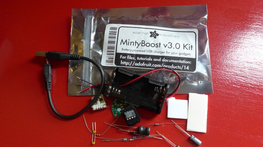
One of Adafruit’s first kits was the MintyBoost USB charger which you solder together yourself, runs off of two AA batteries and fits in an Altoids mint tin. Throw one in your bag and they are super handy when you need an emergency phone charge. It’s worth the looks you get when plugging your phone into an Altoids tin. I’ve built five of these and from those builds thought of two improvements I wanted to make. The first problem was if the batteries were left in for an extended period of time they would eventually discharge to the point that they would leak and I killed two MintyBoosts this way. The second thing I wanted was enough room in the case to fit a small charge cable, so I decided to design and 3D print my own enclosure.
Today I’m going to show you how I approached this project and printed this custom MintyBoost charge pack.
I’ve Got a Plan
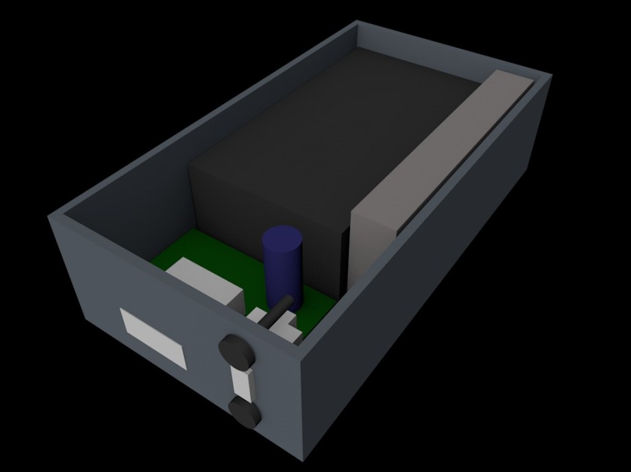
To solve the battery meltdown problem, I decided to install a switch to completely cut power when not in use. I found a small switch at RadioShack (yes, some still have electronics parts) and the perfect short USB cable from Newegg. With these in hand, the first task was to build stand-ins for the all the parts so I could layout the box. I measured everything with calipers and used simple shapes to represent the greenboard, batteries, switch and cable and screws. I could shuffle these around to determine the best layout.
3D Modeling: An Expected Journey
For almost all of my projects including the Octopod, I have been using Cinema 4D, an alternative to the very popular Maya. Both are polygon modelers typically used for animation, visual effects, motion graphics, and video game assets. My introduction to modeling and animation was with Maya, an industry standard but I kind of hate it. One of my professors, an industry pro, would say, “Maya defaults to broken.” I find it overly complicated and a chore to use but it can also do amazing things and a lot of studios have workflows built around it. Cinema 4D is a German program, seems to be very popular overseas and is used often for motion graphics (flying logos, intros and outros to programs, etc) in the States. It has seen heavy use in films such as Iron Man 3 and Serenity but is still not as popular as Maya. I just prefer the interface, structure, how it works and particularly the modeling tools, so I’ve stuck with it but this is just one newbie’s opinion.
Cinema now allows you to model with real measurements vs generic units so I tend to work in metric any time I can because it makes things so much easier. (Why can’t we get on board with this?) When polygon modeling, I will look at the object I want to make and break it down into simple shapes to figure out the best way to tackle it. For example, when I built the Buckaroo Banzai Jet Car, I blocked it out with primitive shapes that are supplied in the program and kept refining them and adding detail to arrive at the finished product.
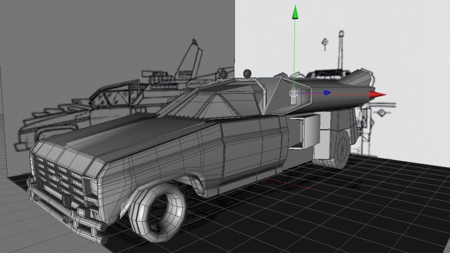
Modeling the MintyBoost box was pretty straightforward; I roughed it out with a cube and…turned it into a box. The trick was to figure out the best way to add details and the tolerances needed to fit the switch and other components. Check out the video in which I demonstrate ways to model the box.
The Print: There and Back Again
So after modeling a rough version of the box using my stand-ins I wanted to print a quick prototype on the MakerBot. When printing with FFF you can control the quality and speed of the print a few different ways. You can change the layer height which determines resolution, specify how thick the outer wall should be, designated by ‘shells‘ and how solid the item should be by the percentage of fill.
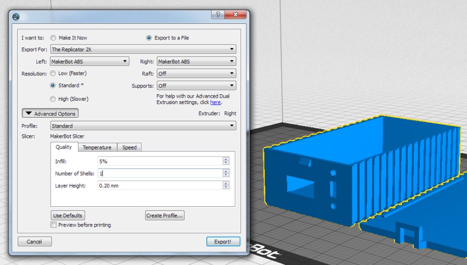
The ‘default’ resolution for most FFF printers is currently .2mm (or 200 microns) and .1mm for ‘fine’ prints, I generally use .2mm for my prints including rough drafts. Shells will change the thickness of the outer wall by ‘drawing’ the outer shape for each shell you designate. More shells will make your object stronger but too many shells can cause problems when printing small items or intricate detail. My MintyBoost box has very thin walls so it’s better to do 1 shell with fill rather than 2 shells. The wall thickness is so small that 2 shells would take up most of the area, leaving no space for fill which would result in gaps on the top of the print.
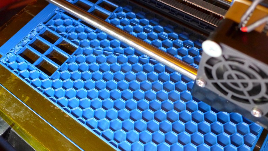
Finally, the higher the fill the longer it takes to print but it will also be stronger. If you specify anything below 100%, the slicing program will typically use a honeycomb pattern to meet your fill %. I should also mention that the actual speed of the print can also be set. This is simply how fast the print head moves while printing. Most decent printers can handle 90 – 150 mm/s travel speed and use acceleration algorithms to help make nice prints. In comparison, my unmodified Thing-O-Matic couldn’t go much past 20 mm/s without making crappy prints.
For the rough box I used .2mm layer height, 1 shell and 0% fill. This produced a flimsy box that printed very fast but since I just needed to know if everything would fit inside, strength didn’t matter. I’ll often write the print specs and other redesign notes right on the prototype so I know exactly how it was printed. At this point I might change the position of component openings, the size of the box, etc. and then do another test print.
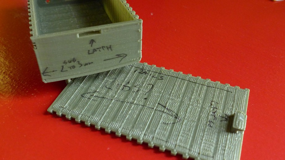
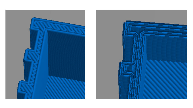
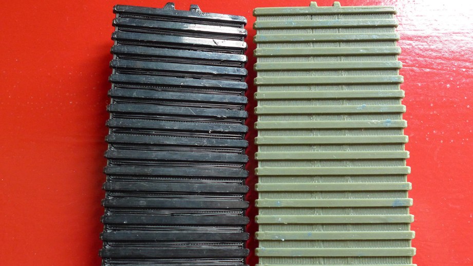
Once I was happy with the layout I added a simple latch and rails on the lid to keep it from shifting. I jazzed up the box with some fins which made it more challenging to print and is a good example of how 3D printing can be fiddly. Due to the design of the lid, it has to print top-down, meaning the fins will be the first thing to print. This also means that the gaps between the fins will have nothing to hold them up while printing which is called bridging. With FFF you can usually bridge small distances but the first time I printed the lid, the slicing program printed everything parallel to the fins so there was nothing to hold up the recessed areas and it got messy. I had to rotate the part in the slicing program so that it would print perpendicular to the fins and produce a better print.
A Charged Phone for All
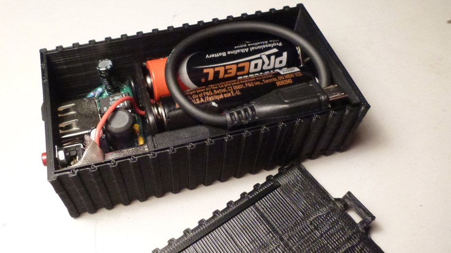
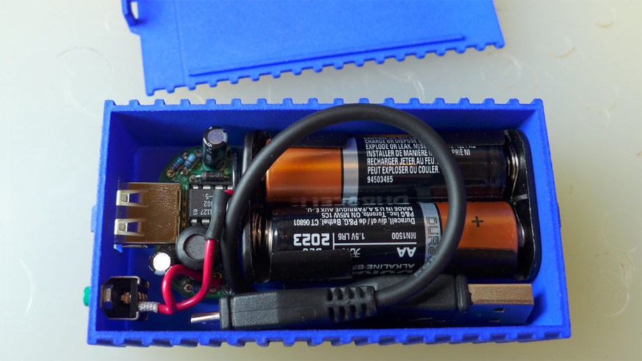
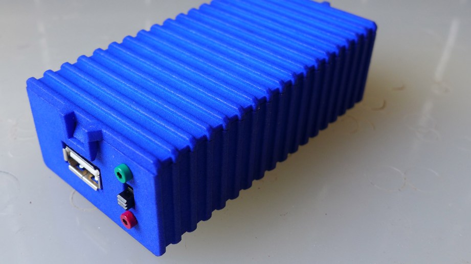
For the final print I used a higher infill for strength and everything fit in as expected. The switch was a bit of a pain to install and should be done before putting any of the other components in. I love having the cable as part of the package and the switch has allowed me to keep batteries installed indefinitely. I liked it so much that I decided to get a print done at Shapeways in the strong and flexible material. I also had it polished which takes off the rough edges for a nicer finish (this can lose fine detail on intricate pieces). I’m really pleased with the print and carry it in my bag all the time.
I hope you’ve enjoyed the MintyBoost walkthrough, post any questions in the comments and I will try to answer them all. If you have your own printer, the files for the MintyBoost Box can be downloaded from my Thingiverse page. The part numbers for the switch and cable are included and there’s a link for the Shapeways version if you would like one but don’t have a printer.
All photos and images courtesy Sean Charlesworth
Maker Profile: Investment Banker Turned Artist
What happens when you put traditional artists in a high-tech workshop with access to the latest in CNC equipment? That’s one of the goals of Autodesk’s Artist in Residence program, and this week, we’re profiling a few of the makers given free rein in this awesome workspace.
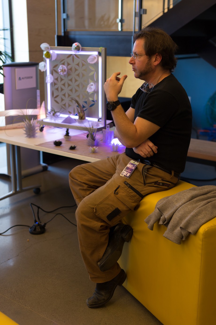
Timothy Lipton is not an artist. A former equity analyst and investment banker, he moved to San Francisco 12 years ago to work with start-ups. A background in consumer electronics and green tech, three years ago Lipton co-founded ReAllocate, a non-profit with the aim of connecting cognitive surplus with meaningful projects. At 42, he’s a maker, but not an artist at heart, so Autodesk’s Artist in Residence program gave him the opportunity to both create and be creative.

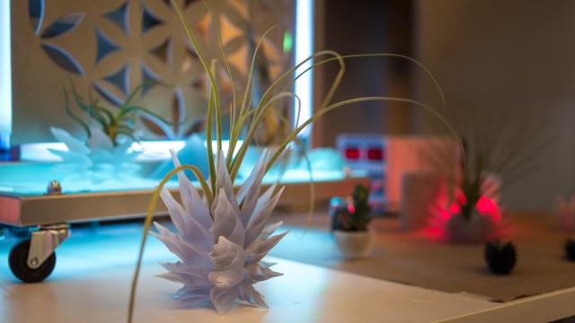
“I wanted to explore organic and inorganic shapes in space,” he said, noting how he began to play off the idea of sacred geometry, or six-sided figures. For example: he created one shape by starting with a basic design, rotating it a few degrees, stacking the image and then repeating, resulting in a spiral-like design that, in his mind, lends itself to being a plant holder.
For Lipton’s artist in residence project, he wanted to engage with the workshop’s equipment while exploring subjects and concepts he found interesting. With that in mind, he built a sculpture that combines elements of sacred geometry, the collision of organic and inorganic matter, and one of San Francisco’s most iconic pieces of imagery: the Golden Gate Bridge.
“I live about a block from the water, and I’m a sailor, so the bay is one of the big reasons I moved here,” Lipton said. “The bridge is such a big piece of that, so it was fun to play with that in an art piece.”

While exploring sacred geometry and the intersection of organic and inorganic matter, Lipton’s original plan was to build a six-square-feet living herb wall. He ultimately concluded that, between the hydroponics and other systems that would need constant attention to maintain, an installation of that size would be too much of a burden upon a gallery or other art space. Instead, he opted for one-third of that scale, using a flower of life design for the pattern.
Construction began by laser cutting a piece of cardboard to test the size of the frame, “just to see if the proportions made sense.” Next came another trial using plywood, this time adding the flower of life pattern. Once he was satisfied with the design, it was finally time to laser-cut in steel.
For the bridge itself, Lipton used an STL file he found online of, in his mind, the piece that epitomized the bridge’s look: the spires. Since he doesn’t have a strong technical background, Lipton relied on collaboration with other artists and designers for many of his CAD files.
“I think in many ways it’s similar to how a DJ doesn’t necessarily have to spend the years to be amazing at the piano or the guitar or all the existing instruments,” Lipton explained. “They’re able to take existing content and create unique pieces of art with that. In many ways that was a leverage opportunity for me since, because I was able to turn to my friends for computer aided design files, that freed me up to really explore what the equipment can do.”
Collaboration was essential for another major aspect of Lipton’s piece: the lighting. For that, he turned to another artist in the program, Lumigeek’s John Parts Taylor, who helped by creating Arduino shields to control both the spires’ color and the series of lights moving through a diffusing tube, an emulation of cars travelling through the fog.
Lipton’s two-month residency has ended now, but he remains fascinated by the concept of what’s capable with digital design tools. After all, when you can make almost anything, what do you make? Either way, he’s thankful that a workshop of this caliber is going out of its way to engage with artists, fuel the creative juices, and see what happens.

“I’m a creative person and a tinkerer, yet I’ve never been an artist before,” Lipton said. “It’s really been a transition from someone with a finance background to someone who’s given this wide range of tools and to create and be creative. I was able to create art for the first time in my life.”
Adam Answers – 2/4/2014

Maker Profile: John Whitmarsh’s Mixed Media Sculptures
Sitting amongst the chocolate shops, posh restaurants, America’s Cup hangars, and other touristy attractions of San Francisco’s Embarcadero district lies Autodesk’s Pier 9 workshop—an office space filled with 3D printers, CNC routers, a woodshop, metal shop, and even a test kitchen. But you might wonder: why would Autodesk—a software company—assemble a mountain of high-tech hardware that dwarfs any private man cave and rivals public membership-based workspaces such as TechShop? The short answer is that since the majority of the equipment in the space runs on Autodesk software, having said equipment close at hand lets software developers stay abreast of the newest, coolest ways its digital tools are being used. To that end, the company created an Artist In Residence program to put those machines to good use.

Open to anyone 18 or older, Autodesk’s AIR program aims to put these cutting-edge tools into creative hands and, essentially, let them run free. Artists accepted to the program are granted unrestricted access to the Autodesk facilities, giving them the chance (as well as the training) to use the kind of top-level production equipment they might never otherwise be able to access. Sculptors who’ve previously worked with clay, for example, can experiment with a paper 3D printer. Collage artists can tinker with the latest 3D scanners. The idea is to let loose Picasso in Tony Stark’s lab. In return, the artists deliver at least one Instructable guide (also owned by Autodesk) for a project they worked on during their residency (which can last up to several months). The real reward, though, are the innovative and unexpected ways these creative minds find to use that equipment.
We met with four of these artists in Autodesk’s workshop to see what they’ve come up with, and will be profiling one of them each day this week.

John Whitmarsh didn’t set out to be a sculptor, but it’s clear he’s exactly where he should be. The 41-year-old California native originally attended Syracuse university for film school, but after graduation quickly found a much greater interest in sculpture.
Having never taken any actual sculpture classes in school, Whitmarsh honed his craft as most self-taught artists do: reading books, watching videos, going to stores and simply asking for advice whenever possible. During this time he mainly worked in construction doing tile installation for residential remodels. This went on for the better part of 10 years, dividing his time between art and sculpture in the studio and high-end kitchen and bathroom remodels to pay the bills.
“The first couple years of doing it, nothing really turned out that nicely at all,” Whitmarsh explained. “Everything just didn’t look very good.” But while things were rocky to start, Whitmarsh’s sculpture work continued to grow and improve, and he’s now spent a handful of years focusing on art alone.
Whitmarsh was turned on to the Artist In Residence program by Noah Weinstein, a creative programs manager at Autodesk whom he met while selling some of his equipment. “I met Noah Weinstein because he bought a drill on craigslist that I was selling,” Whitmarsh said. “When I applied for it, it was actually in the old office — now that I’m here I’ve realized like, ‘Wow, this is ten times better.'” Better is right. The new Autodesk workshop has opened a world of possibilities for the sculptor, who usually works with wall installations — a choice he said stems from the premium on floor space in densely populated cities.

One of Whitmarsh’s main projects is a large shelving unit with handwritten text cutouts and inserts which together create an embossed look. He wanted to use his actual handwriting, but after an attempt using Livetrace—a software that converts bitmaps into vectors—produced files requiring too much cleanup, he resorted to rewriting the entire thing on a Wacom tablet.
Once he had vector files for the text, Whitmarsh used a Shopbot CNC-router—one of the workshop’s computer-controlled woodworking machines—to cut the lettering out of plastic cutting board material. He then used the same vector file to cut a large sheet of steel on the workshop’s waterjet cutter, specifying a very slight offset to allow for the plastic lettering to fit in.

Outside of wall sculpture, Whitmarsh enjoys the aesthetic look of things coiled and bundled upon themselves—a “rat’s nest,” he calls it—such as the look of rebar that has been crushed and compacted after the demolition of a building or freeway. However in many cases, recreating such a thing in the studio would be essentially impossible.
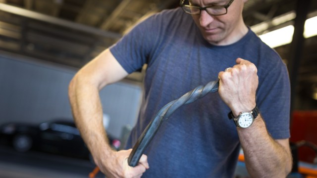
“I like exploring the physicality of materials,” Whitmarsh explained, noting how people often wonder how he twisted or bent a seemingly unbendable piece of metal, only to realize it’s not metal at all. Take an I-beam for example—normally used as a support beam in a building’s structure, I-beams are, more or less by definition, unbendable. But using 3D modeling software, an I-beam shape can be twisted or bent, then—using a 5-axis router—cut from wood or some other material.

“People look at this and say, ‘How did you twist the metal? It must have taken a ridiculous amount of force—how did you do that?'” Whitmarsh said. “It looks really heavy, but then they touch it and realize it’s actually very light.”
But while access to the workshop has allowed him to easily pursue and complete these such projects, Whitmarsh said he doesn’t like using a computer aided machine “just because you can.”
“My idea is to do things the simplest way possible,” he said. This might mean casting a mold instead of 3D printing an object, or vice versa if you can’t cast it or don’t want to spend time making a mold for a single object. “It all depends on whatever is the simplest way. A lot of times using computer aided machines would be the simplest way, but if there’s a better way, then that’s how I do it.”

While Whitmarsh never really put his film degree to good use, his original interest in visual media has begun to creep back in, especially with the degree to which modern video equipment has simplified the entire filmmaking process. “It’s mainly taking the shape of documenting my work and getting videos together of the actual making-of process,” he said. “I think people are really interested in the process behind it.”
“They have no idea what it takes to actually make something—they just see the end result, and they don’t realize how many tools and screw-ups and everything went into it.”
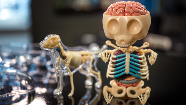
Show and Tell: A Gummi Bear’s Anatomy
Back in September, we toured the workshop of artist Jason Freeny, who sculpts the anatomical interiors of pop culture toy characters. His sculptures are one-of-a-kind custom creations, but collectors can now pick up a mass produced Gummi Bear figure designed by Freeny. Norm shares this new toy kit along with another plastic anatomical find.