This week, Will, Norm, and Loyd discuss PRISM, the next-gen console wars, the Playstation 4’s price, wearing Google Glass, and the largest four-sided dice ever. Oh, also WWDC stuff, including new Mac Pros, new MacBook Airs, iOS 7, and OSX Sea Lion (Mavericks is a dumb name).
Inside Adam Savage’s Cave: The New Laser Cutter!
Adam equips his workshop with an old friend and powerful tool: the laser cutter. We learn how Adam used laser cutters in his model-making days and see a demonstration of the process of designing and cutting a simple object. Always be cutting!
The Google Hangout Q&A – 6/11/2013
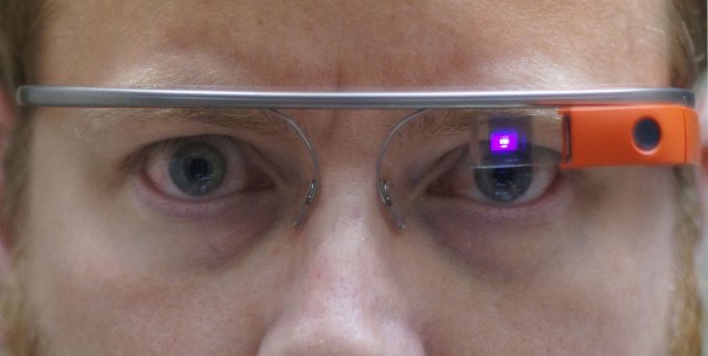
This week, we try something a bit different. Adam and Will hop on a Google Hangout to answer questions live, as they’re submitted from folks in the audience. Topics discussed included Google Glass, the NSA, Adam’s box obsession, the ultimate bug-out bag, and a whole lot more.
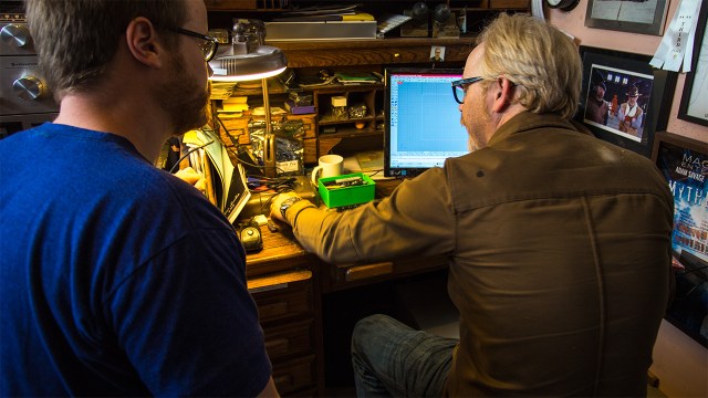
Inside Adam Savage’s Cave: Hacking a Flashlight for Adam’s EDC
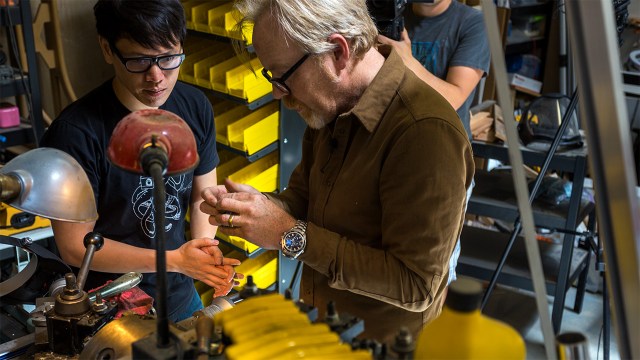
Not too long ago, Adam showed off the contents to his everyday carry, which included his go-to LED pocket flashlight. That flashlight was lost, so Adam needs to replace it with another that has a proud button. That means modifying a flashlight with a recessed button. To the lathe!
Episode 172 – Put a Hat On It – 6/6/2013

On this week’s show, Norm regales the gang with tales of Switzerland, Gary regales the gang with tales of New York, and Will really nails the intro. All that, plus WWDC rumors, a handful of Computex announcements, Omni VR, the EFF’s podcast patent troll fight, E3 preparations, and a whole lot more. If you’re looking for the tech news, just skip ahead to the one hour mark.
The Volpin Project, Part 10: Illumination and Audio
Static props are fine if you’re making a sword or a shield, but when it comes to a space combat theme, everything has to have LEDs in it. The Needler in particular has (at the time of this writing) 33 LEDs, but I may find a spot here and there to drop a few more in before finally calling the whole thing finished. Sound can also lend a bit of fun to a replica, and while it’s always going to be difficult to match the on-screen experience that a surround sound system gives you, it’s still fun to pull the trigger and not have to make the “pew pew” effect yourself.
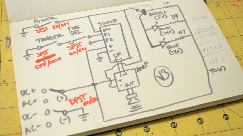
For the Needler, I started out by making a list of the things I wanted it to do and where/how it needed to do them. Lights had to come on via a switch, and I wanted a “start up” noise to accompany this effect. I also wanted a push button trigger that would toggle between automatic and semi-automatic fire. From my experience with audio in props before, I also knew I’d need a small amplifier to bump up the volume. All of that was a bit much to organize in my head so I drew out a few schematics. The above sketch was version three, not final, but good enough to start working.
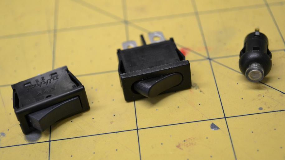
There are a myriad of switches available to hobbyists and a lot of fun tricks you can pull off when you start feeding them into one another. For example, I needed one button to control both semi and automatic firing noises, but the sound chip I decided to use can’t be programmed to swap effects. To get around this, I wired the trigger switch output into a second toggle switch that selects either the automatic or single firing sound effect. The trigger itself is a momentary push button that glows blue, because why not? If you’re digging around for components like these, go to digikey.com–their online catalog takes some getting used to for navigation, but the selection is fantastic.
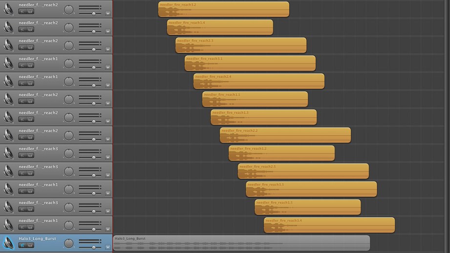
I had some help with the sound effects on this project, and I’d like to thank Aaron over at The History of Halo for ripping the audio files for me from Halo: Reach. In order to get the full auto fire clip correct, I edited a bunch of the single fire effects together into one audio file.
When I first outlined this project several months ago I said I’d be putting an Arduino microcontroller into it to control the lights and sound. I also said that the techniques showcased here would be on a somewhat introductory level, and the more I thought about explaining coding for props, the less I felt that would be in the spirit of the project. Additionally, I’m not really the best in the world when it comes to programming an Arduino, and if you’re going to have a teacher, it’s better to have one who knows the material. Luckily, there’s a heap of helpful solutions around these hiccups that I can talk about.
Enter replicaprops.com–I’ve used their sound modules before in my Portal Gun projects to play gun firing noises as well as the snarky dialogue from a talking potato. Getting audio into a prop couldn’t be easier; just send the files you want and directions on how you want them to activate (such as “push once to play” or “hold down to play”) and a few days later you get a pre-programmed chip in the mail, ready to go.
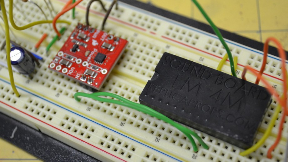
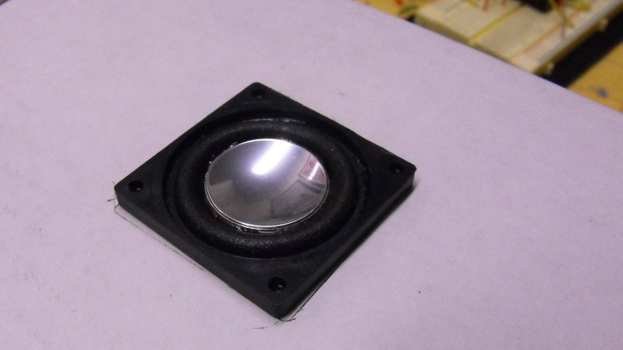
The amp–the red chip shown in the rear of the photo above–comes from sparkfun and is perfect for this application because of its low power use and mono output. That chip comes pre-assembled so all that you’ll need to do is add power, signal, and a speaker to get going.
A handy piece to have around when you’re mocking up your circuit is a breadboard. In the photo above with the red amp, it’s the tan piece of plastic with all the little holes in it. Generally speaking, sets of rows and columns on the breadboard are connected, so that ICs or boards plugged into the open terminals can be jumpered to switches, LEDs, resistors, or any other electrical component desired. I’ve mocked up the audio and illumination circuit first here to make sure that everything is working as planned and there aren’t any faults in the circuit diagram I drew out above.
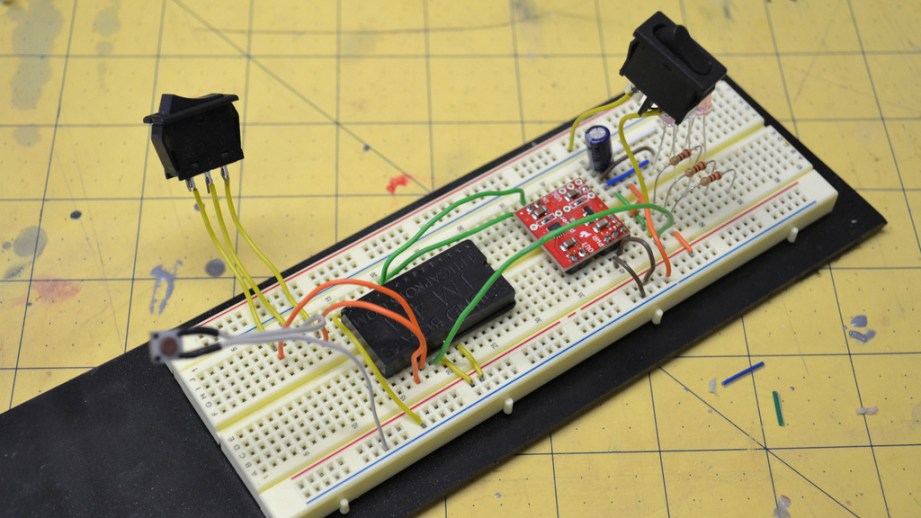
There’s a lot going on in that shot, so I put together a small video that showcases the features and explains what’s going on far better than my ability to write it all out.
That’s the audio portion sorted out, time to focus on illumination. For this project, and really for pretty much 90% of the props people will want to make, LEDs are the way to go. I buy mine from superbrightleds.com and while the prices there are a little higher than what you might find from buying bulk on eBay, I’ve never had a dead bulb. Also, every light on every project I’ve made since 2008 is still burning strong. Once you glue a prop together, you don’t want to have to tear it apart a few months later to replace a burned out LED because it was $.10 instead of $.65.
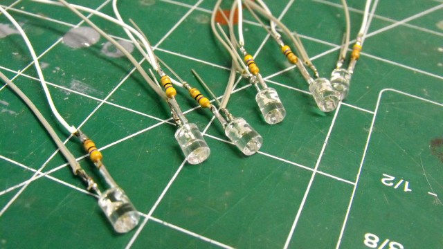
LEDs need resistors to properly limit the voltage they receive so they illuminate properly without being damaged. There’s an equation for this, but there’s also a handy website! With a few values for your bulbs and power supply, you’ll have the proper resistors sorted out in no time by going to ledcalc.com. For my LEDs, I prefer to solder the resistors (to the positive lead, that’s important!) directly to the end of the bulb if I’ve got the room in my prop to do so. This makes things simpler when connecting wires together, since you can just bridge all positive and negative leads from separate components into thicker gauge wire to eventually go to a power supply.

Shrink tube will help reinforce your solder joints here and keep things from shorting out.
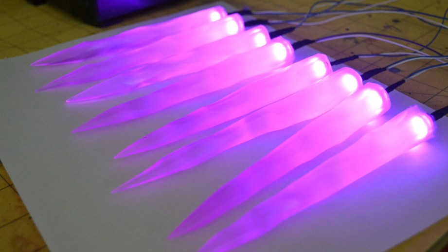
Embedding the LEDs into the needles will be no problem. Each pink LED is individually wired and a 5mm hole is drilled into the back side of the needle. When it comes time to mount these into the body of the gun, I’ll cut off the base at an angle, leaving the straight hole intact to make sure the light shines the correct direction. This is just eight, but the finished gun will have 14 illuminated spikes.
The front “emitter” areas are a bit trickier. The light in these components shines out through irregular holes at the front and very thin lines towards the back. I had originally intended to trim these spots out of a hollow casting and insert a thin piece of acrylic in their place, but getting a uniform thin emitter casting proved… difficult.
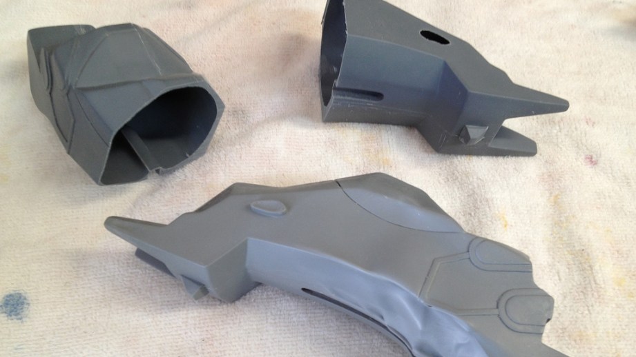
The solution here was to go back to what I’d done earlier with the needles and cast these parts in clear resin. The crystal clear used before is expensive though, and the entire part didn’t need to be optically transparent, so I decided to use a cheaper alternative: Smooth Cast 325. This urethane resin cures slightly cloudy and a sort of yellow-white, but it will be perfect for my needs.
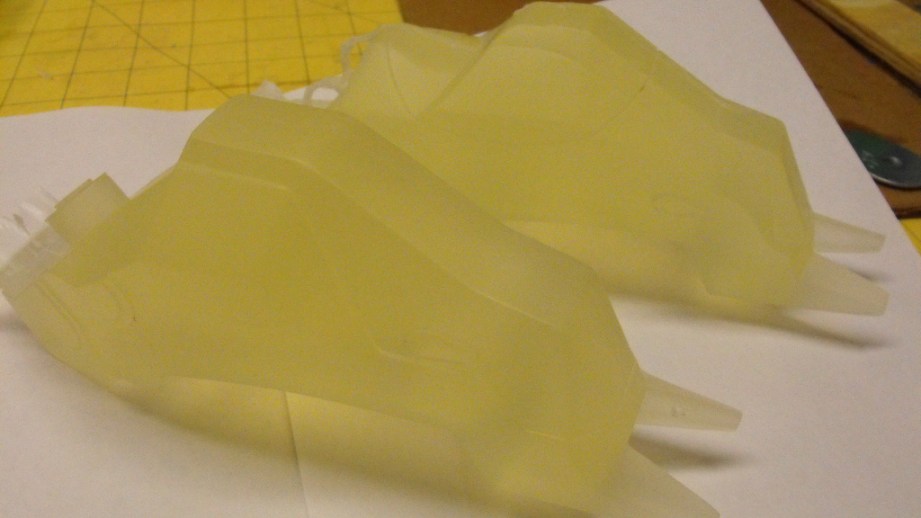
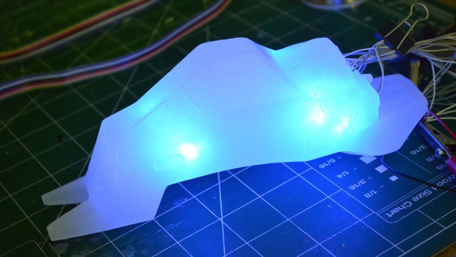
That photo isn’t particularly impressive, but the plan is to embed six blue LEDs into these semi clear parts. After the emitters have been painted and weathered, the paint on the lines and forward holes will be scraped away, letting light out! I’ve got a couple tests so far, and the results are promising, even with just a simple LED flashlight.
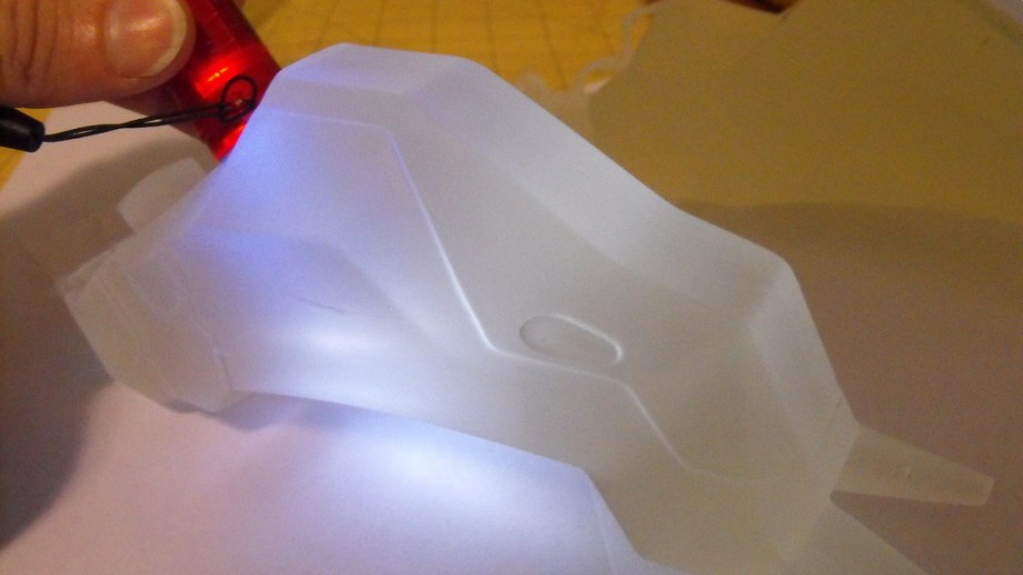
I had a scrap casting sitting about from a dud pour (remember last time when we talked about pressure pots removing unwanted bubbles from clear resin? Here’s a perfect example of what it looks like without pressure!) so I drilled a few holes to test out the best placement of the LEDs. Good thing too, as my initial idea turned out to be full of hot spots.
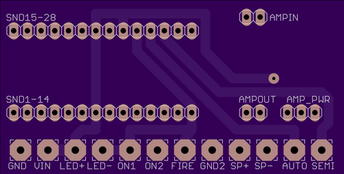
The last thing I’ll mention is a bit of a luxury, but when it comes time to install all of these components into a finished prop I prefer to have things on a custom printed circuit board. While it is possible to solder chips and leads onto a piece of generic perforated circuit board and jumper all the connections, custom PCB printing has recently become inexpensive enough for hobbyists to employ even with strict budget projects, provided you don’t mind a couple weeks for production time. I designed these boards in CadSoft’s EAGLE board layout editor, and while that is a very powerful program (even the free version!) it does have a somewhat steep learning curve.
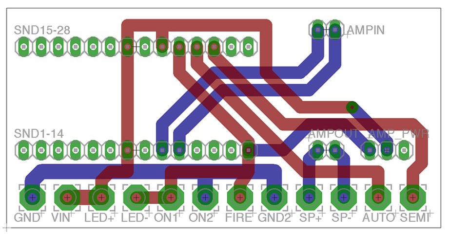
This board will let me add screw terminals for all the off-board connections like switches and LEDs, making final assembly much cleaner and faster. There are dedicated pads for both the audio chip and amplifier and every connection between them is made on the board so there’s no worrying about wires coming loose. I’m currently using oshpark.com for PCB printing, and my boards are set to arrive in about two weeks. For three of these pieces, I was only charged $16!
That’s it for this installment! Next time I’ll start sanding and fitting the cast parts together, drilling mounting holes and preparing everything for paint and weathering. It’s been a long road so far, but there’s now light at the end of the tunnel.
The Volpin Project, Part 1: Introductions
The Volpin Project, Part 2: References and Blueprinting
The Volpin Project, Part 3: Selecting Materials
The Volpin Project, Part 4: Taking Shapes
The Volpin Project, Part 5: Bondo Strikes Back
The Volpin Project, Part 6: Details, Accents, Refinements, and Mockups
The Volpin Project, Part 7: Introduction to Moldmaking
The Volpin Project, Part 8: More Complex Moldmaking
The Volpin Project, Part 9: The Casting Process