Bits to Atoms: How Carbon’s CLIP 3D Printing Technology Works

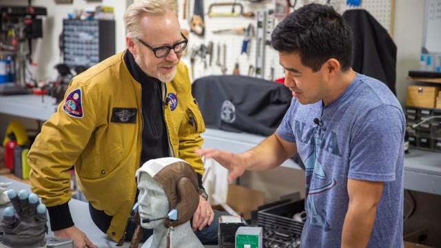
Carbon3D (now going by just Carbon) has been all the buzz in the 3D printing community with their M1 printer which uses CLIP technology to greatly increase the speed and quality of DLP printing. The Tested team visited Carbon HQ outside of San Francisco to see exactly how this new tech works.

As we’ve discussed before, 3D printing with UV-cured resin tends to offer the highest level of detail and choice of material (compared to 3D printing processes like FDM). Let’s review the options. SLA (Stereolithography), such as the Formlabs Form 2, draws and cures each layer of resin using a laser. DLP (Digital Light Processing) uses video projector technology to draw and cure each layer in one blast. Polyjet uses an inkjet-like head to draw each layer on a platform and is cured via a UV light unit. Now, Carbon is introducing CLIP (Continuous Liquid Interface Production) which drastically increases printing speeds and improves surface finish–but how does it work?

First let’s look at the normal SLA or DLP printing process. The model is ‘drawn’ layer by layer via laser or projector onto a print platform and must go through a peel process after each layer. Exactly how the peel is done varies by printer and technique but it generally consists of the print platform, moving out of the way so that the resin can be redistributed for the next layer. This slows down the printing process and also requires generating support structures to hold the print steady.

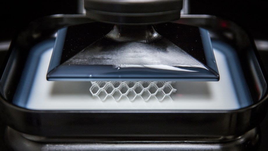
Carbon’s CLIP technology eliminates the peel process by using an oxygenated layer of resin between the resin tray window and the print itself. This layer creates a dead zone which allows the print to emerge continuously from the resin tray, skipping the peel process. OK, but how does that happen? The secret is in the M1 resin tray, called a ‘cassette’ which holds the resin and has an oxygen-permeable window in the bottom which a DLP unit shines light through. Carbon won’t divulge exactly how the chemistry works but the cassette allows a resin layer between the window and where the printing happens to be oxygenated which inhibits the curing process while still allowing the DLP light to shine through and solidify the resin above. I know–it sounds crazy.

https://www.youtube.com/watch?v=UpH1zhUQY0c&rel=0&wmode=opaque

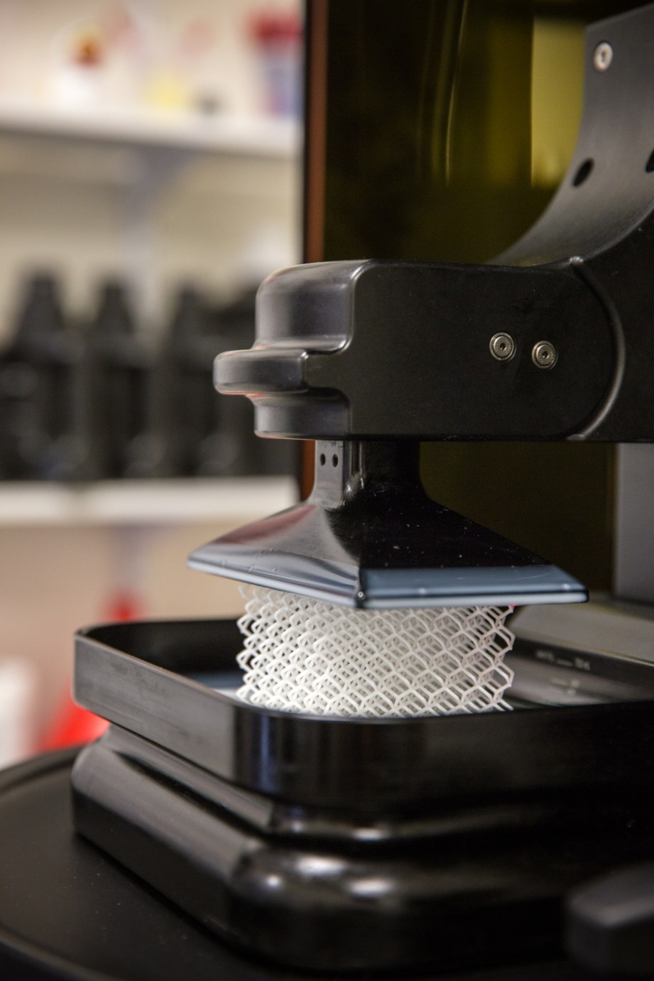
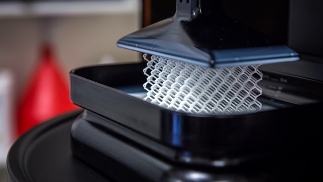
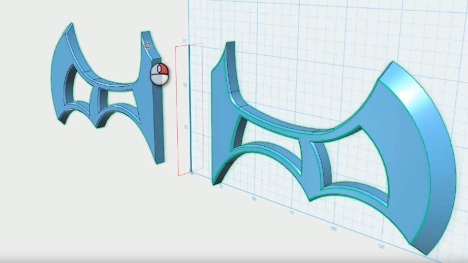
One of the big advantages of this process is a drastic decrease in print times. We observed a test print actually emerge, Terminator 2-like, albeit a little slower, from the vat of resin while we watched for 15 minutes. The M1 prints at a fixed 75 micron resolution which falls in the middle of one of my favorite pro machines–the 3D Systems ProJet 7000 HD which can produce prints at 125-50 microns resolution. And while the M1 may not go to as fine a resolution as other printers, the nature of the CLIP process tends to blur print layers to where they are much harder to notice.

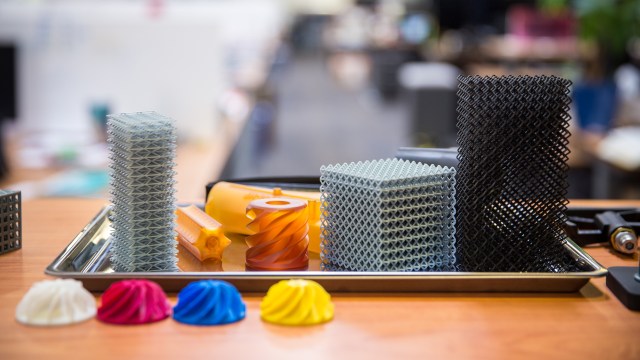
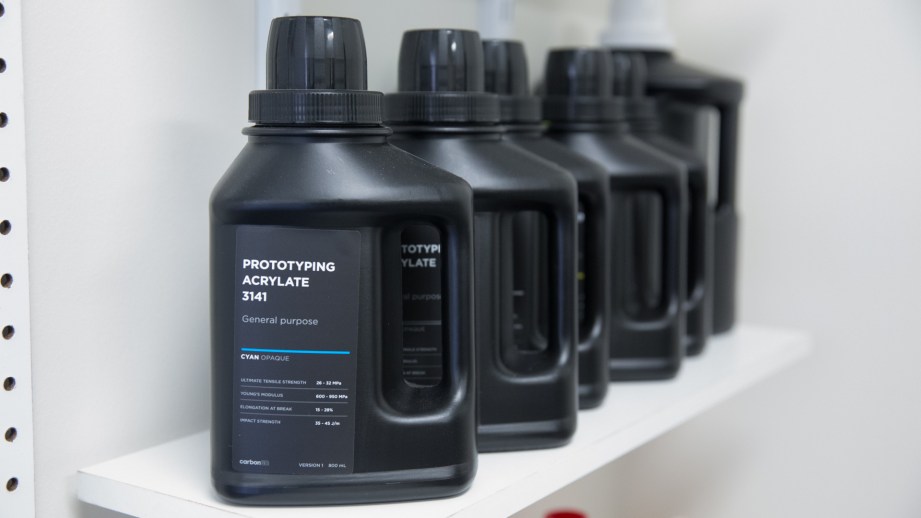
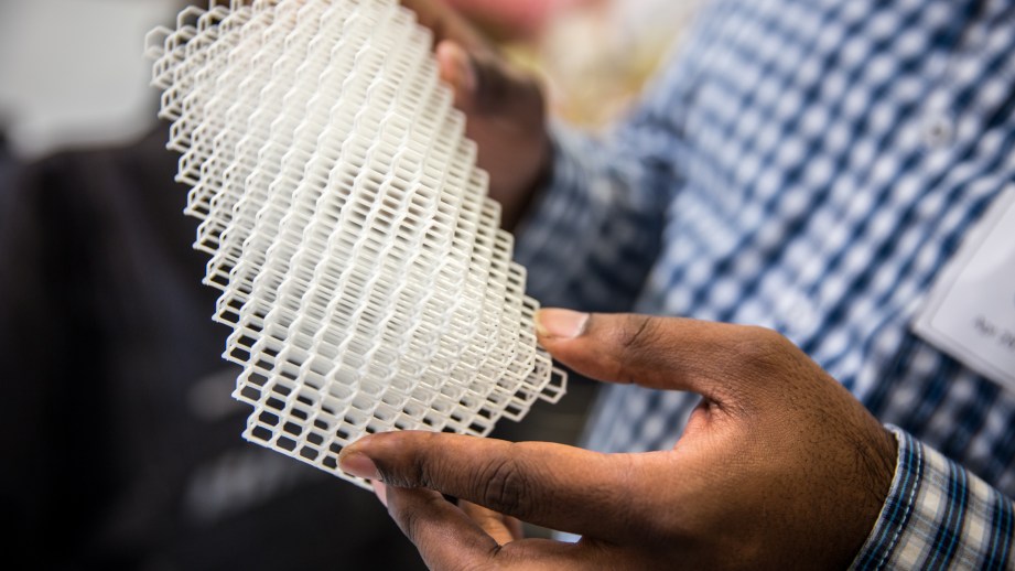
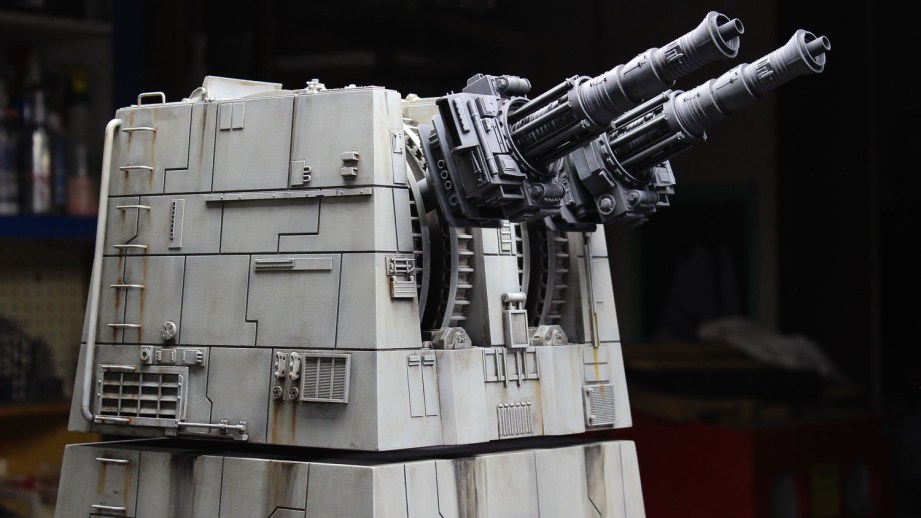
Carbon did not set out to just make printing faster but to make this an actual production machine for making parts to be put directly in the field. 3D printing is often referred to as rapid prototyping as it can be used to easily make multiple iterations of a part. Often the 3D printed materials are not suitable for long-term use and must ultimately be manufactured by traditional methods. Carbon has introduced a line of industrial-grade materials that are meant to be put in direct service and have been successfully tested by companies such as BMW and Legacy Effects. The parts we saw were truly impressive such as a vent with the strength of glass-filled nylon and heat resistance up to 500℉. Or the super-flexible material which was some of the nicest I have ever seen 3D printed. Our demo print was done with the prototyping resin which is designed for exactly that – fast production of prototypes. It was a very fine print and the finish was beautiful, and although not as strong as the other resins, it was still quite sturdy.

The Carbon CLIP resin cassette. The Carbon CLIP resin cassette.

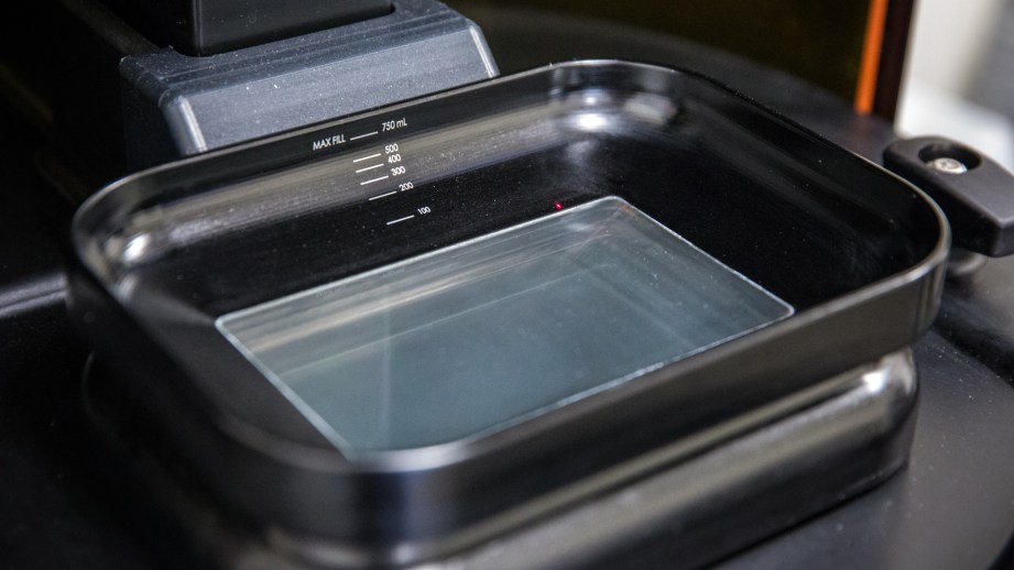
These fancy materials do pose some challenges when printing. First, the resin cassette currently does not auto-fill, so the exact volume of the print must be calculated and that quantity of resin placed in the cassette. Second, other than the prototyping resin, most of the other resins are two-part, meaning that they must be mixed before going into the cassette. Once mixed, they immediately start to cure and must be printed with right away. This means there’s no re-using extra resin left in the cassette – part of the reason for careful measurement. Carbon said they are able to re-purpose established industrial resins which allows them to make such strong, service-ready parts but also requires the mixing process.

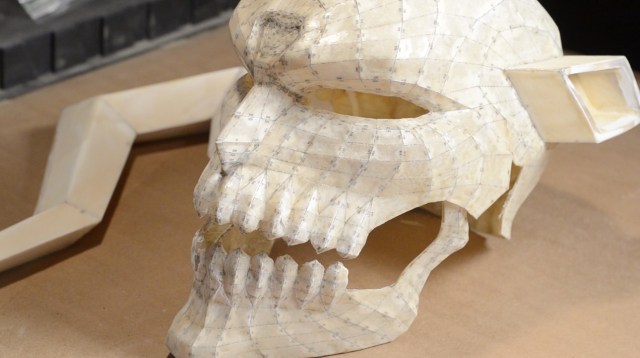
Post processing is the same as other resin printers–the printed part is washed in alcohol to remove any liquid resin, then ‘baked’ under UV light for the final cure. The part can be sanded or even sand blasted to smooth out any print lines and can even be painted.

Carbon envisions the M1 as an actual production machine, making ready-to-use parts and its speed helps to make that possible. However, it’s also priced for an industrial market as it’s only available to lease at $40,000 a year with a minimum term of 3 years and that’s just for the printer, two cassettes and a resin sampler pack. Training, installation and needed accessories will run you another $22,000. While expensive, if manufacturers can produce field-ready, print-on-demand parts quickly, this may not be a bad way to go.

With so much hype surrounding 3D printing, I see more and more too-good-to-be true products – everyone is making a cash grab. With Carbon, I was truly impressed with the quality of parts that the M1 produced and I look forward to see where and how the CLIP technology will be used. I can’t help but wonder if we will see it on a desktop unit any time soon. It’s this kind of tech that will keep driving 3D printing further from its rapid prototyping origins to full-blown production and custom manufacturing–pretty cool stuff.

Meet the Carbon M1 Super Fast 3D Printer

Watch this complex object get 3D printed in less than 15 minutes. Sean and Norm visit Carbon, the makers of the M1 3D printer, to get a demo of this new super fast 3D printing technology working in real-time. We chat with Carbon’s VP of Product, Kirk Phelps, to learn how the CLIP 3D printing tech works, and why it’s more than just about really fast prints.

Shot and edited by Joey Fameli
Music by Jinglepunks

Introduction to 3D Modeling for Prop and Costume Making

Through a weird and winding job path, I landed a pretty compelling career as a prop and costume maker, but I that’s not where I intended to go when I started. When I was a starry eyed youth, I had ambitions of being a professional 3D modeler and animator for movies and video games! I even went to school for, and got a degree in, 3D computer art, modeling, and animation. Then life happened and I never actually got a real job doing any of that. I did, however, end up in a highly creative field that requires me to keep my fabrication skills finely honed and to keep pushing myself to make things better and faster.

Why should I learn 3D Modeling?

Enter my 3D modeling skills! In prop and costume making, I’ve found that being competent at 3D modeling has been an amazing boon to the productivity and quality of the pieces I produce. The obvious first reason is the current 3D printing craze. 3D models of props can be made real with affordable desktop printers at an alarming rate. This rapid prototyping makes iterating prop designs a snap! Not only can props be made completely from printed parts, but those prints can be used to design, scale, and test parts quickly and easily.

These blaster grips were printed several times to adjust for the scale and thickness to get them just right. These blaster grips were printed several times to adjust for the scale and thickness to get them just right.

3D drafting can also provide a bevy of other benefits to the prop maker, even if one doesn’t own a 3D printer. One of my other favorite outputs for my models is Pepakura. Many makers rely on the pep files that other makers release online to print out and make their own Iron Man helmets and armor pieces, but what if nobody has modeled the specific piece that you want to recreate? You’re going to have to model it yourself!

If you make your own Pepakura models, you have complete control over the size and form of the final pieces. This flexibility will give you the power to make pieces that will fit whatever body you plan to put them on. Plus you can design the Pepakura to work with materials of a variety of thicknesses (EVA foam vs. cardstock).

Finally, 3D modeling your prop or costume pieces can be an incredible first step in planning and visualizing your build before buying and modifying your stock materials. I modeled every piece of my District 9 Rifle in SketchUp before starting the actual build. This allowed me to make detailed blueprints that I could lay out flat and plan exactly how much material I needed to buy in a plethora of thicknesses.

A 3D modeler can do the same for their costume pieces by modeling the parts around a stock human form. We will usually do this when planning large, bulky armor sets so that we can check out the scale and silhouette of the costume and plan our build accordingly. Even if these 3D files aren’t used for 3D printing or Pepakura, it’s still incredibly useful as a visual aid for your costume fabrication.

Isn’t 3D modeling software expensive and difficult to learn?

It used to be the case that all 3D modeling software cost thousands of dollars and you needed to take extensive courses just to understand the basics of how to use them. This was the state of reality when I got started in the late 90s. I was fortunate that my high school had 3D Studio Max installed on some of the computers and I was able to blunder my way through the smattering of user made tutorials available on the internet at the time. So, I made due at a snail’s pace until I got a decent, in-depth education in college using Maya.

The times have changed for the better! Nowadays there are a variety of 3D modeling software packages, both open source and made by big companies, like Autodesk, that won’t cost you a dime! Even better, since big companies have a stake in getting you to use their software, they a have an incentive to make easy to follow video tutorials on how to use their software. Some of my favorites are the tutorials from SketchUp, 123D Design, and Fusion 360. I used these tutorials along with their free software to make models for many of my recent prop and costume builds.

All of the options above are for a more CAD like modeling experience, but if you’re looking to get into polygon modeling for pepakura, video games, or animation, then look no further than Blender. This is a free, open source 3D modeling application similar to Maya. Want something that’s a little closer to traditional sculpting? Try Sculptris!

Those are all fantastic, free 3D modeling applications and there are many more out there. You have no reason to not go download them and give them a try!

Note: Links to all of the mentioned software are at the end of this article!

Where to get started?

If I were just getting into the 3D modeling game these days, I’d give Tinkercad or 123D Design a go. Both are free and aimed at the entry level modeler. I have since hit a wall in what these applications can do, but the newbie will find them extremely easy to use and will be churning out wonderful little prop models in no time. In fact, Tinkercad was designed to teach CAD to children and is available as a web app. Talk about a seriously low barrier to entry!

What types of projects are good for beginners? Well I wouldn’t start with a full set of Iron Man armor. An “appropriate level of ambition” is required when learning any new software. Otherwise you might hit a wall quickly and rage quit in desperation. Pick a small prop piece, something that you think is neat like, say, a thermal detonator. Something with fairly basic geometric forms that are easy to make from default primitive forms will be an excellent first 3D modeling project.

One of the first things I made in 123D Design was a batarang. One of the first things I made in 123D Design was a batarang.

Once you start to sharpen your 3D modeling claws, you should really push yourself to try some more ambitious builds! If you’re anything like me you’ll run into the limits of what some of the free, beginner level software can do and start looking to move to the next level.

What do the pros use?

Ever since I got a 3D printer, I’ve been dabbling with as many of the 3D modeling software options as I can get my paws on. The majority of my training is in Maya and if you work for a large video game company, you probably use that, 3ds Max, Rhino, or some other proprietary software suite. I’m a small independent company and the cost of those packages are currently outside of my reach, and that’s just fine. I’ve been having a lot of success with Fusion 360.

Most of the modeling work I do is for very geometric forms. Things like robots, helmets, and space guns are excellent fodder for CAD based applications like Fusion 360 and, since I’m a small startup, I can get it for free! So far it’s been absolutely incredible for cranking out 3D models that are just perfect for 3D printing and the results speak for themselves.

My Mister Handy 1:6 scale robot. Modeled in Fusion 360, 3D printed, finished with traditional model making techniques, molded, cast, and painted. My Mister Handy 1:6 scale robot. Modeled in Fusion 360, 3D printed, finished with traditional model making techniques, molded, cast, and painted.

For me, one of the most compelling features of Fusion 360 is their “sculpting” mode, which allows you to create pieces in a free form manner, much like the polygon or sub-d modeling I know and love. This means than when I have a slightly more organic form to build, like the collar under Mister Handy’s eyeballs, and I can’t figure out how to do it in CAD, I can just eyeball the sculpt by pulling, pushing, and extruding the faces, points, and edges of a soft 3D form.

If you’re more interested in woodworking projects, the standard seems to be SketchUp. Their community is also really great about creating 3rd party plugins to solve specific problems for a variety of 3D modeling projects and styles. I used it to design a bench for my CNC router.

No excuses! Give 3D modeling a try!

Especially if you own a 3D printer, you owe it to yourself to dive into the wonderful, glorious world of 3D modeling. Hopefully I was successful and you’re already downloading a pile software as you read this! It can be extremely rewarding to rebuild your favorite prop piece in a 3D digital world. For a more in-depth look at using software like 123D Design, check out the 3D modeling and printing tutorial content we’ve put together on the Punished Props site. Happy modeling!

Some 3D modeling software for you to try

Bill Doran is a professional prop and costume maker. You can find more of his work at PunishedProps.

Ryan Nagata’s NASA Spacesuit Replicas

Prop maker Ryan Nagata is obsessed with NASA spacesuits, and has made the best replicas Adam has seen. While at his workshop, Adam and Ryan geek out over the process of fabricating fake spacesuits, including fabric selection, sewing, building hardware, and weathering. Plus, Adam gets a surprise!

Shot by Joey Fameli
Edited by Adam Isaak
Music by Jinglepunks

Episode 350 – Class M Planet – 5/12/16

Lots to talk about this week on This is Only a Test, as we finally see the announcement of Nvidia’s Pascal video cards, both the new Call of Duty and Battlefield games, and some rumors leading up to next week’s Google I/O conference. Plus, we celebrate the transit of Mercury in A Moment of Science!

Building a Studio Scale Death Star Laser Tower Model, Part 1

Hello Tested! My name is Dave Goldberg. I’ve been a professional model maker working in the movie and television industry for more than thirty years. These days, most all of the visual effects shots that use to be done with models are done with computer graphics, but there is a movement of people, like myself, building Studio Scale replicas of classic models from old movies. Studio Scale is a term used to describe replica models that are the same size as the original filming models.

Like many people, Star Wars: A New Hope was a seminal film for me. It came out during my freshman year in college and immediately changed the direction of my education and career. From that moment on I wanted to build models for the movies. While I built models for many movies and televisions shows over the years I never got the opportunity to work for a Star Wars film. But now I can do the next best thing, build them for fun!

For this project I’ll be making a studio scale replica of one of the Laser Towers from the Death Star seen during the final battle in the film. I am also excited to be making this an “Open Source” project. I’ll be posting the model files for anyone to use freely for non-commercial purposes. They may be used to create your own model but not to create parts, kits or finished models for sale. The repository of model files is here.

These files are for the model as I will be building it outlined in this series of articles using CNC routing, laser cutting, kit bashing, some 3D printing and good ol’ fashioned scratch building. However, if desired, a competent 3D modeler should be able to convert the master model so that the entire Tower can be 3D printed, either at Studio Scale or smaller.

Reverse Engineering from Reference Photos

“Reverse Engineering” is a term used to describe the process of figuring out the size and shape of something using photographs. This can be done in 2D or 3D, although reverse engineering in 3D requires some pretty sophisticated software and detailed information about the photos must be known such as the focal length of the lens, exposure aperture and distance to subject. 2D reverse engineering is basically digital tracing over a photo and then determining its size using landmarks of known size and/or some educated guessing!

Fortunately there are a wealth of photos of the original Laser Tower model on the web. The original filming model was on public display a few years back part of the touring Star Wars Exhibition and several fans shot extensive photos of it and posted them online for the benefit of fellow modelmakers. There are also some nice still images of the model in the Special Features section of the Blu-Ray disc of the movie.

The trick to successful reverse engineering is to start with a photo shot square on to the model with as little perspective in it as possible. Most digital drawing and modeling programs will allow a photo to be imported and drawn over. For modeling projects like this one my software of choice is Rhino 3D, which allows me to import photos and create 2D drawings, as well as 3D models which can be used for 3D printing, laser cutting and CNC routing, but more on that later.

The trick to successful reverse engineering is to start with a photo shot square on to the model with as little perspective in it as possible.

Once I had drawn the basic outline of the turret and some key details over the photograph it was time to establish the actual size for the model. Sometimes the actual dimensions or scale of a model is known, or even better, it was possible to place a ruler next to the model during photography from which the size can be determined. Neither of those were a possibility in this case. However the laser barrels on the model were actually the engines from a known plastic model kit, a Revell 1/32 scale Mig 21, and I was able to purchase one of these kits on EBay. This would prove valuable both later on as a “donor part” for the model but also now as a way of determining the size of the turret by scaling the photograph and the drawn outlines to match the measured size of the kit part.

3D Modelling

Using the 2D over-drawing as a guide, as well as other photographs, I proceeded to 3D model the Laser tower in Rhino 3D. This involved careful examination of the various reference photos from different angles as well as some educated guesses as to what areas might look like that could not be seen clearly. Over time a pretty comprehensive 3D model emerged.

For the film, only the turret and a short section of the tower below it were actually built, as those were all that were necessary for the planned shots. I wanted my tower to be a little more imposing, so I extended the bottom of the tower to almost double the height of the model to 3 feet. This also allowed me to have fun making up some additional details lower on the tower not seen on the original filming model.

One of the great powers with using 3D modeling software in the design of physical models is that it allows you to not only work out the design but methods of fabrication as well. I broke up the solid mass of the tower into the various pieces from which it would be assembled. This “virtual model kit” allowed me to fine tune the construction long before starting the physical build. A digital form of “measure twice, cut once!”

From the 3D model of these individual parts accurate line drawings could be extracted. These drawings were then exported as .dxf files for use in CNC routing.

Next time, we’ll discuss how I constructed the casework for the model structure. In the meantime, post your questions and comments about this build in the comments section below. See you next week!

Photos and images credit David Goldberg

David Goldberg is a professional modelmaker, propmaker, visual effects supervisor and mechanical designer with more than 30 years experience working in the motion picture, television and theme park industries.

Part 1: Sourcing Reference

Part 2: Building the Casework

Part 3: Fabricating the Details

Part 4: Painting and Weathering

Captain America: Civil War SPOILERCAST – Still Untitled: The Adam Savage Project – 5/10/16

We kick off this summer movie season by reviewing Captain America: Civil War! As with all Spoilercasts, we start by discussing the movie without giving anything away, and then dive deep into what we thought about specific scenes and characters. Adam also talks about some recent show finales he’s enjoyed, and why he loves dramatic comedies.

How to Build the PinSim Virtual Reality Pinball Machine

The PinSim cabinet is essentially the first eight inches of a real pinball table. I designed it to play VR pinball games, but it works just as well as an interface for traditional flat screen pinball games. The following instructions will help you make one of your own. I’ll cover the most basic build first and then look at a few optional upgrades.

The electronics are based on Teensy LC and employ the incredible MSF-XINPUT library by Zachery Littell. This new library fools the computer into thinking the Teensy LC is an Xbox 360 gamepad, thus minimizing latency and maximizing compatibility. It even supports force feedback rumble! Zack spent time improving his library to assist with this project, so major thanks to him.

There are many possibilities for cabinet material. My original cabinet was cut from foam core but wood will provide a more lasting frame. Just make sure to consider the material thickness before cutting the sides of the cabinet. The graphics below illustrate the exterior dimensions and hole placements, but the diameter of the drill holes will depend on the buttons you choose to use.

Let’s start with the parts you’ll need.

Parts

Parts Notes

PCB: You can use a Large Breadboard but I strongly recommend picking up the PCB I designed from OSH Park to simplify the wiring. They come in sets of three, so you can share a set with friends or just keep the spares.

Teensy LC: While Teensy LC is pin-compatible with the more expensive Teensy 3.2, I recommend using Teensy LC due to the support for 20mA current on a few pins that I use for lighting optional LEDs. You can buy a pre-flashed Teensy LC from me at the link above.

Joystick: This is used to conveniently navigate game menus, but you could use a gamepad instead. If you do include a joystick, just mount it according to its mounting plate wherever you think it fits best.

Accelerometer: The accelerometer is used to simulate nudging the table. Make sure to mount the PCB in the precise orientation and position indicated below for the most accurate readings.

Cabinet Build Instructions

Cut your cabinet sides based on the dimensions below and drill holes for your buttons, joystick, and legs, centering where indicated. The holes for the leg bolts can be a little tricky, especially with wood, because they enter at the corners at 45 degree angles. I recommend drilling these from the inside out.

Cabinet Dimensions Cabinet Dimensions
Front of the Cabinet Front of the Cabinet
Sides of the Cabinet Sides of the Cabinet
Back of the Cabinet Back of the Cabinet

Wiring Up the Controls

Mount the PCB/Breadboard on the underside of the top panel so that the accelerometer is horizontally center and the text “ADXL 345 Digital Accelerometer” is facing the player. This probably means that the PinSim PCB is mounted between the joystick and the front edge of the cabinet like in the photo below.

Wire everything up according to this image if you’re using a breadboard or just use the labeled terminals if you’re using my PCB. Note that all components can share a common ground wire. The joystick pinout can be found here.

IMPORTANT: If you’re not installing a plunger, connect the “PLUNGE” terminal on the PCB (Teensy pin 15) to GND. This will disable the plunger. Failing to do so will leave the pin “floating,” causing the virtual analog stick to move unintentionally.

If you didn’t buy a Teensy LC from me, which comes with firmware already installed, download the compiled firmware and flash your board using the Teensyloader application. You’re welcome to compile the firmware yourself but the XInput library does require some Teensyduino files to be overwritten. You can find instructions on GitHub.

You’re done! Plug in the Teensy LC using a USB micro cable and it will power up. You can test the PinSim by launching the Windows USB Game Controllers app from the Control Panel.

PinSim Cabinet compared to a Pinball Cabinet PinSim Cabinet compared to a Pinball Cabinet

PinSim Upgrades

LED Light

Let’s put the light inside the Start button on the front of the cabinet to use. If you connect it to the LED-1 terminal on my PCB (or pin 16 on a Teensy LC), it will blink when powered up. It actually flashes between 1-4 times, mirroring the 4 LEDs around the Xbox logo on a real gamepad. This is a useful indicator since game software often requires controller #1.

Replace the 555 light bulb inside the Start button with a white LED and wire it up (just make sure to run it through a 22 Ohm resistor like it does on my PCB). If you have a 3D printer, you can print my 555 bulb holder.

You can do the same for the bulb inside the Launch Ball button and connect that to LED-2. It will remain steady on.

Rumble Feedback

You want force feedback, right? You’ll need to buy some spare Xbox rumble motors from eBay but they usually run less than $10/pair shipped. If you have a 3D printer, you can also print a couple of my handy mounts.

Wiring the previous two upgrades is pretty straight forwarding using my PinSim PCB, but here is the breadboard wiring if you need it.

Arcade Buttons

You don’t have to stop at flippers. Especially if you have the joystick installed, why not add more buttons and use PinSim as a potential upright arcade controller too? Just drill more holes beside the joystick and connect them to the labeled terminals on the PinSim PCB. For the breadboard crowd, the Teensy LC pinout is as follows.

Plunger

What about a real pinball shooter? I have to warn you, this is a lot of extra work for minimal payoff. The plunge is important for hitting skill shots, but not much else. That said, it does complete the look of the cabinet and you need a plunger for certain Pinball Arcade tables (flat screen, not VR… yet!). For simplicity I’m going to assume you have access to a 3D printer for mounting the sensor hardware.

Here are the additional parts required:

The cabinet hole for a plunger is huge and triangular shaped. And while we can place the plunger at the proper height, we need to fudge authenticity a little and move it an inch to the left in order to leave room for our digital sensor gear later on. Use the following pictures to cut your cabinet hole.

Fire up your 3D printer and print the mount for the distance holder.

Then print the plunger disc that attaches to the shooter rod and reflects the IR signal back to the sensor. Just remove the rubber tip from the plunger, slide on the disc, and replace the rubber tip.

Connect the JST cable to the sensor jack and assemble the mount. Attach the assembled sensor just above the plunger with the wires facing up. The thin, angled plastic mount component should go between the mount and the cabinet, tilting the sensor slightly downward so it points toward the plastic disc. Finally, connect the wires as follows:

  • Black to Ground
  • Red to 5 Volt terminal on PinSim PCB
  • White to Plunge terminal on PinSim PCB

Finally you need to configure the plunger. With the Teensy LC USB cable unplugged, hold down the Start button (Teensy Pin 12) and plug in the USB cable. After a moment the LED-1 should flash rapidly. Slowly pull the plunger all the way out and then slowly allow it to retract all the way back in. The LED should flash rapidly again, and then blink normally. You can repeat this process as necessary, but the settings are permanently stored between power cycles.

While you’re at it, you’ll probably want to re-wire the cabinet Start button to the “A” button and add a second cabinet button to act as the 360 Start button. And as long as you’re adding a plunger, I’m going to assume you’re deep enough into this that you understand why.

See? I told you it was a lot of extra work! If you’re up to the challenge, it’s definitely gratifying.

I just completed assembling my second PinSim, thanks to the great help of my friend and carpenter Christopher Mann. It includes all of the above upgrades plus real flipper buttons and leaf switches (if you do this, make sure to sand down the tungsten contacts). Next up, tidying the cabling and a third cabinet with more precise measurements and a nice exterior finish. Fun!

All photos and images by Jeremy Williams

Premium: Adam Savage in Conversation with Neill Blomkamp

Along with the Alamo Drafthouse theater in San Francisco, we hosted a screening of one of our favorite films: District 9. After the screening, Adam interviewed director Neill Blomkamp on stage to talk about the making of the film, his design aesthetic, and what kind of projects he’s interested in working on. (This full interview is available for the Tested Premium Member community now, and will be released later on YouTube. If you haven’t joined the Tested Premium Member community, you can do so right here.)

Shot by Joey Fameli and Adam Isaak
Edited by Joey Fameli