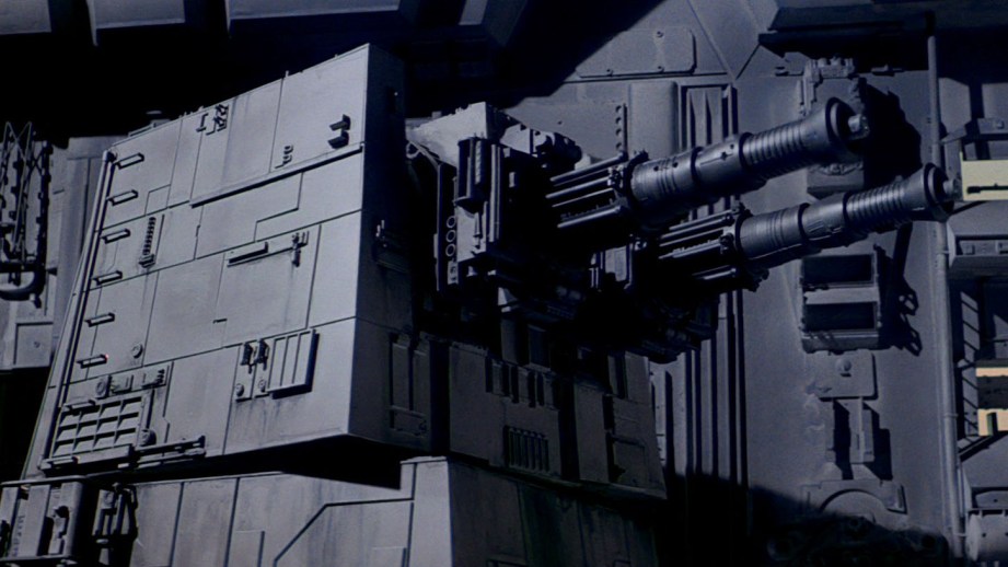
This month, prop maker David Goldberg shares with us his build of a studio-scale replica of the Death Star laser tower from Star Wars. Previously, David covered sourcing his reference, creating a 3D model, and the core structure fabrication. Today is all about the finer details!
The original models built for the Star Wars films were detailed with hundreds of little parts taken from plastic model kits. These parts were often referred to as nernies or greeblies. This was the first time this approach to adding detail for film models had been used to such a great extent and it was one of the defining characteristics of the realistic “used hardware” look of the film. There are photographs of the ILM model shop back in the day showing entire walls stacked high with hundreds of model kit boxes. Models kits of all types and scales were used for “donor parts” but it seems there was a fondness for models of military subjects, especially tanks and other vehicles.
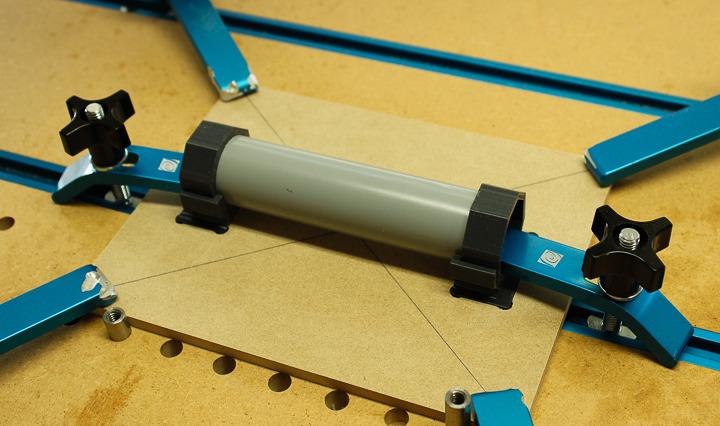
A great deal of time and effort has been spent by members of the Replica Prop Forum (The RPF), Studio Scale Modelers (SSM) and other online sites analyzing photos of the original models and tracking down precisely which parts from which kits were used for the added details. Some of these model kits are still in production and many more are available on EBay, although sometimes at extremely high cost! Other than purchasing the Mig 21 kit to use for the barrels, I decided I didn’t want to spend what could amount to many hundreds of dollars purchasing all of the necessary donor kits, some of which are quite rare. Instead I decided to replicate many of the parts with 3D printing, laser cutting and scratch building. In the end, several ‘authentic’ parts were donated for use on this project by some of the very kind members of the RPF.
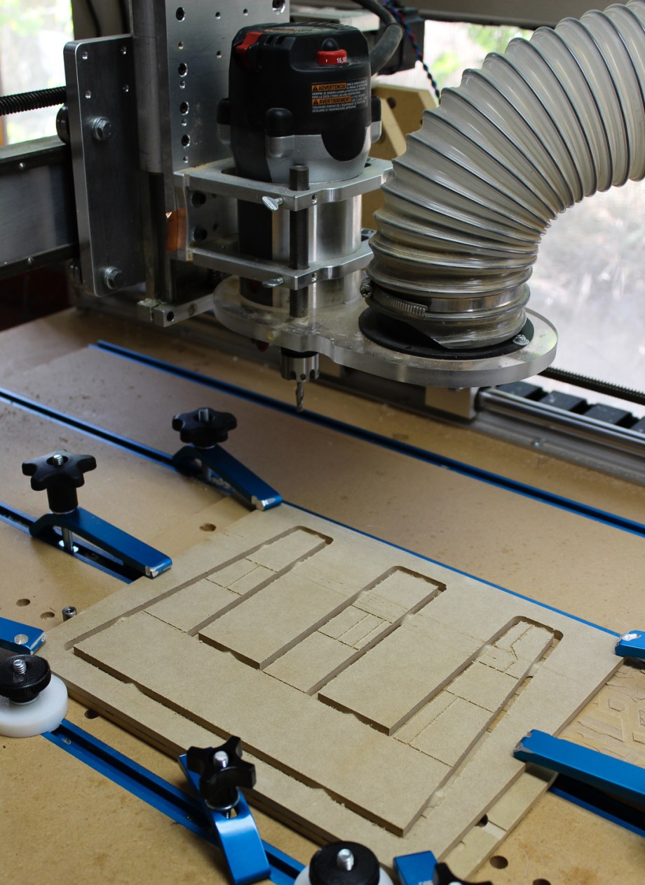
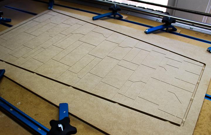
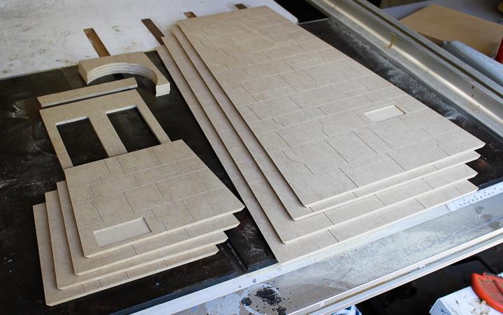
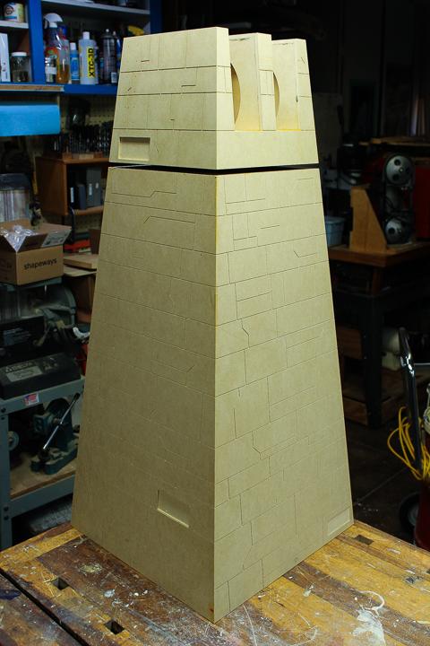
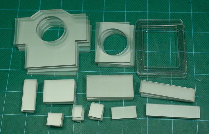
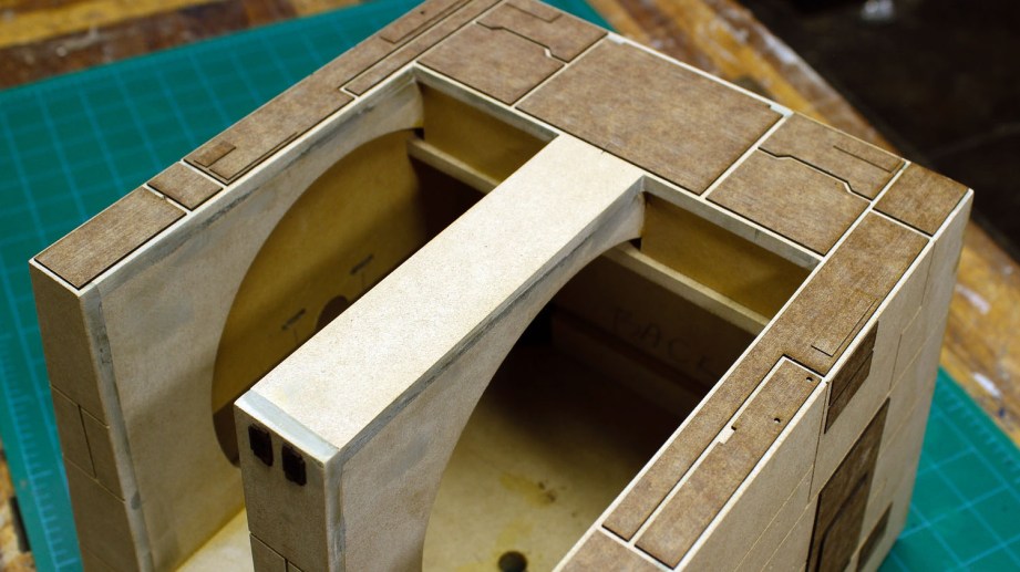
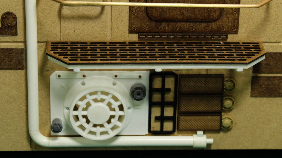
Before applying detail parts some additional layers of plating were needed. Styrene sheet, cut by hand, was used for this plating on the original models but I wanted the benefits of precision and speed that could be achieved using a laser cutter, and styrene doesn’t laser cut cleanly, the edges tend to melt a little. Instead I laser cut the plating panels out of a material called Polybak, a cardboard sheeting which has been impregnated with resin to make it water resistant. Polyback is often used to back cabinet panels in moist locations and as a backer for thin wood veneering. It laser cuts beautifully and takes paint well.
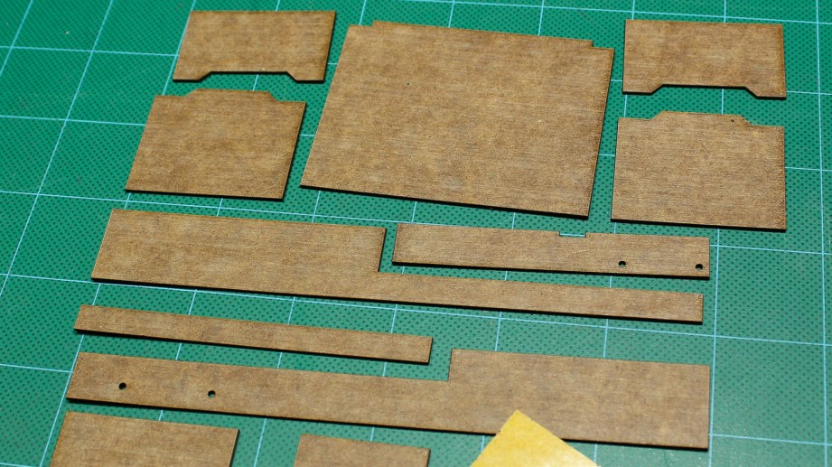
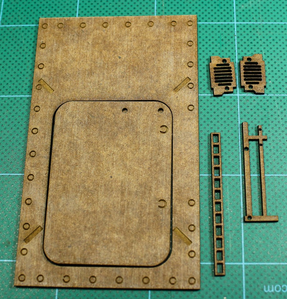
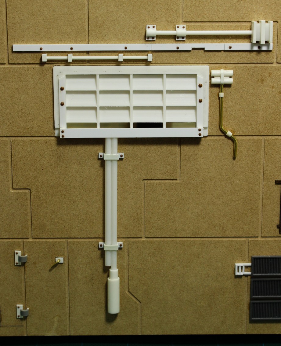
I laser cut a series of panels to go on the top of the tower as well as a bunch of randomly sized rectangular panels that I could stick on the casework wherever desired. Before cutting, I applied double-faced adhesive tape to the back of the Polyback sheet so that to attach the parts all I would have to do was peel off the backing paper and stick the parts down. In additional to the plating, several custom parts were laser cut, some with partial surface etching to represent bolt heads and other details.
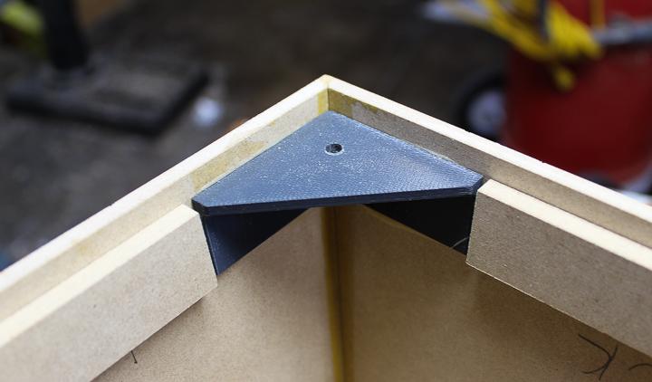
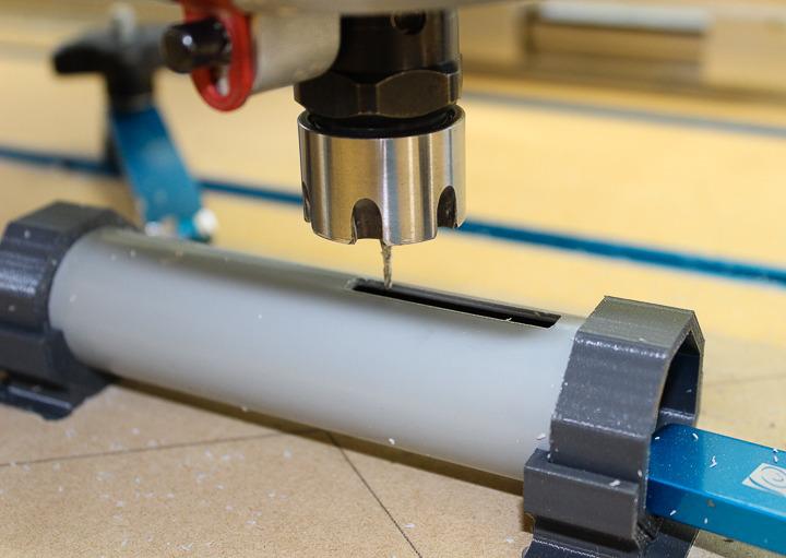
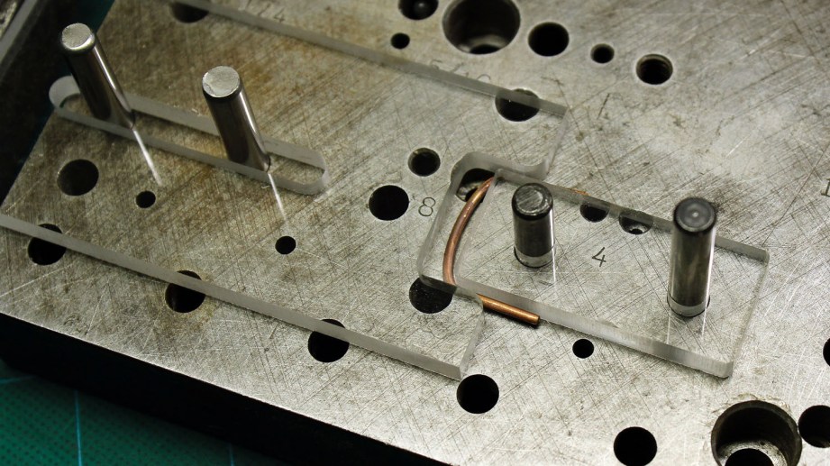
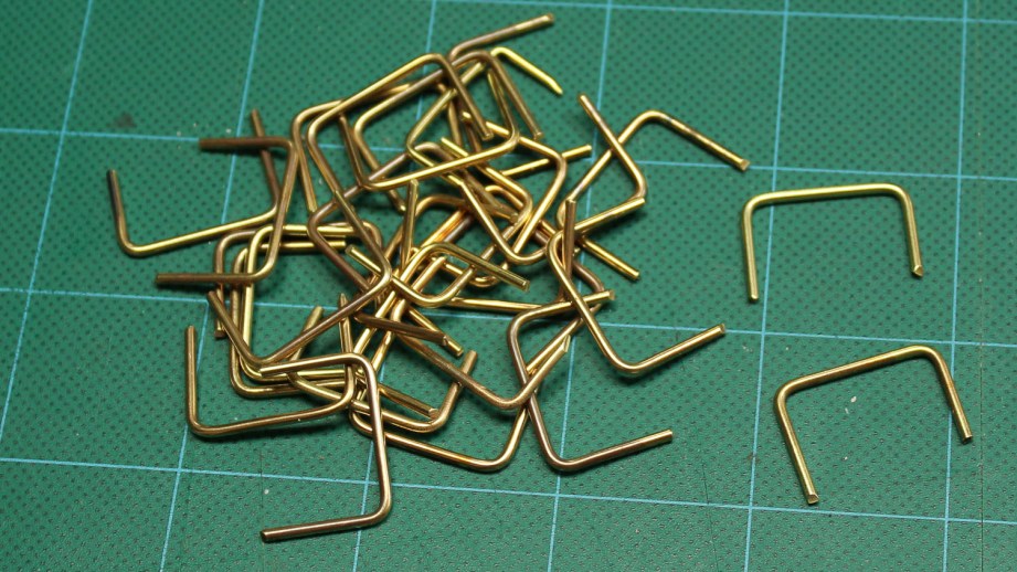
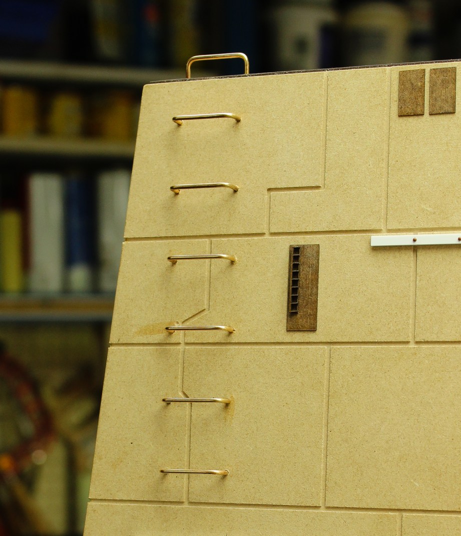
Creating the several dozen bent metal ladder rungs proved to be a unique challenge. The holes for the rungs were precisely drilled into the MDF tower sides as part of the CNC process. To fit these holes, the ladder rungs would all have to be bent to exactly the same width, a very difficult task to do by hand with a pair of round-nose pliers. The solution was to make a bending jig out of acrylic sheet milled to the correct profile with the CNC router and then use these on a jig plate to bend the pieces of brass rod. The acrylic parts were held in alignment on a steel jig plate using dowel pins. The larger piece was able to slide on the pins and the smaller piece was pinned firmly in place. A bar clamp was used to squeeze the two jig plates together with a piece of 1/16 inch brass rod in between. To make the brass rod easier to bend, it was first annealed with a torch.
To bend each rung, an annealed piece of brass rod was placed in the jig between sliding acrylic jaw and the fixed acrylic plate. The bar clamp was used to force the two plates together conforming the brass rod to the desired shape. The finished rungs were then glued in place on the model,
As I had mentioned before, the detail parts on the original model came from (now) vintage plastic model kits. Some of the model makers on the RPF go to great lengths to make sure they have the exact correct part (and only the exact parts) on their models. A process that can take years. I greatly admire that approach, but on the other hand I’d like to get my model built as quickly as possible. As I like to say “Done is my favorite color!” So as I go about detailing the model I’m not really trying to make an exact replica of the filming miniature. I figure it’s a BIG Death Star! There are a lot of Laser Towers on it and there are bound to be some differences! Every studio scale replica is in some ways an artistic interpretation of the original and this one is mine.
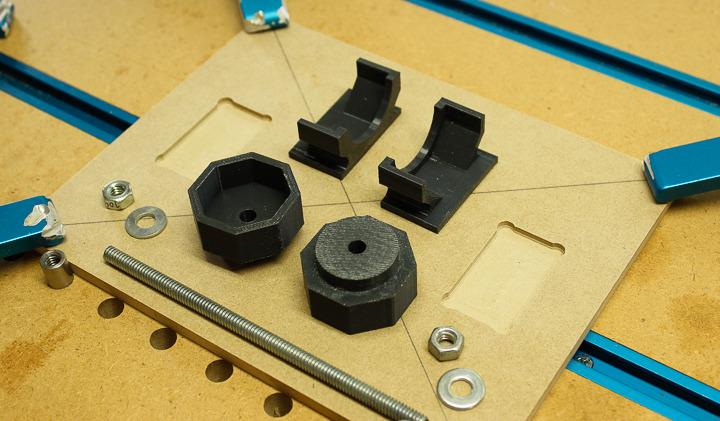
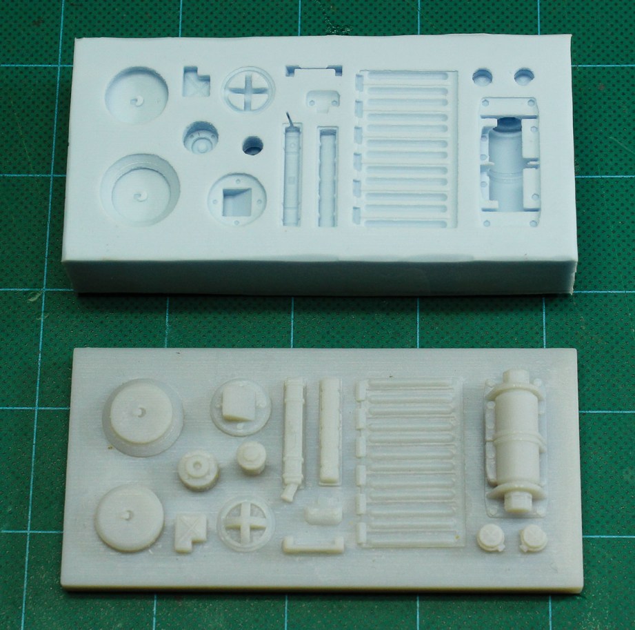
The task of replicating the kit parts used on the original model was done in several different ways depending on the characteristics of the part. Some of the more complex parts were 3D modeled using Rhino software and then 3D printed. Photos of the filming model and in some cases of the individual model parts themselves were used as reference.
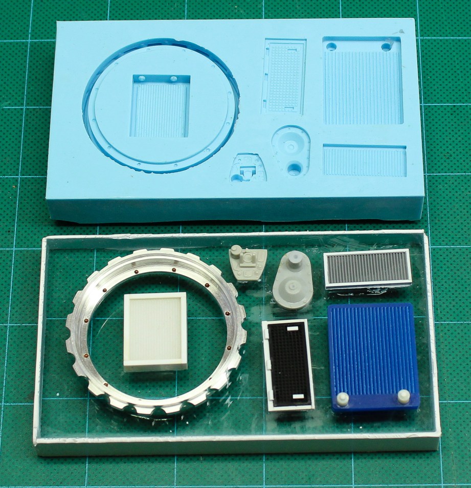
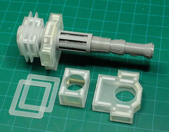
A couple of the larger 3D printed parts were glued directly to the model but as multiples would be needed of many of the smaller parts, silicone molds were made from which urethane resin parts could be cast. The patterns for other flat parts were engraved and cut using the laser and a ring shaped key component seen at the base of the laser barrels was machined out of aluminum using a metal lathe and the CNC router. The castings of these parts, as well as parts from a bunch of other plastic kits on hand formed an extensive library from which I could detail the laser tower.
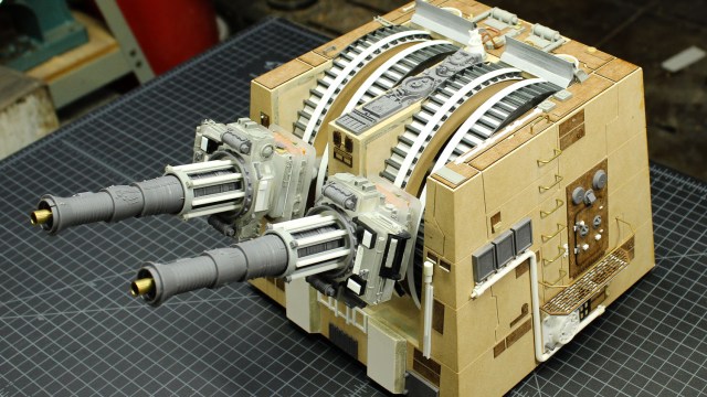
The time had come to start gluing all the various detail parts onto the model. For the most part I used thick super glue to hold the parts in place and a kicker to set the glue instantly.
In addition to the 3D printed, laser cut 3D cast resin parts, some of the details were added the good ol’ fashioned way, built up out of styrene strip and rod along with brass wire of various diameters to represent piping..
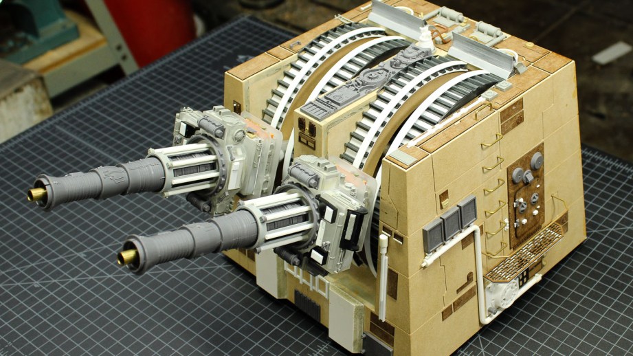
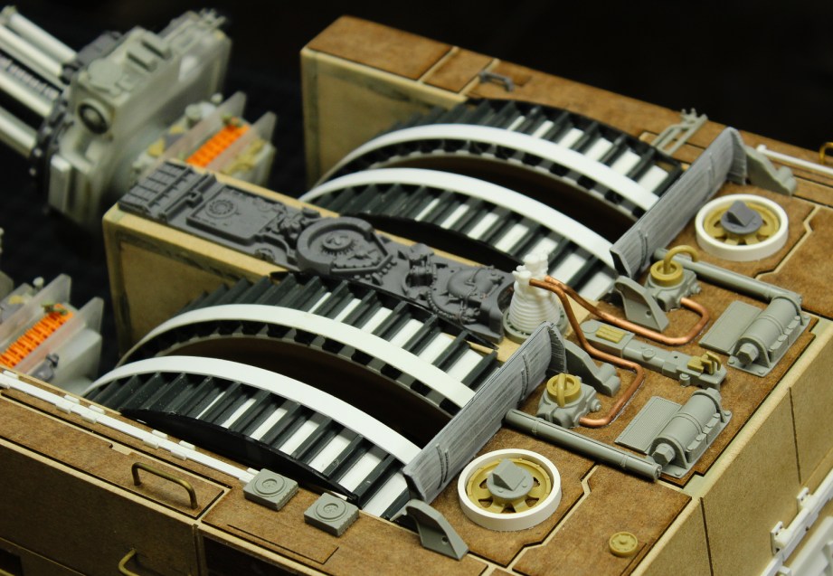
Once all the various detail parts were in place the model was ready to paint. It’s fun to see how the original model makers at ILM reused details from other models they were making for the film. The grey detail casting on the top of the turret in between the two barrel slots is known as the “Droid Strip.” It’s the same detail casting used on the X-Wing Fighter models, on the top of the fuselage just behind the cockpit.
Next up, painting and weathering!
Photos and images credit David Goldberg
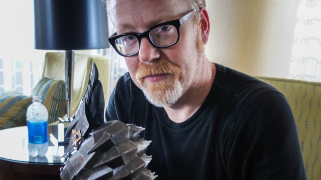
David Goldberg is a professional modelmaker, propmaker, visual effects supervisor and mechanical designer with more than 30 years experience working in the motion picture, television and theme park industries.