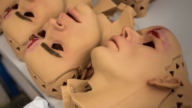
They breathe and they bleed, but they’re not real human beings. These robots, built by the especial effects and fabrication experts at Kernerworks, are incredibly lifelike trauma mannequins used by the military to train field medics. We visit Kernerworks’ workshop to learn how these robots are built and get a demo of their trauma simulation capabilities. See photos from our visit here.
Tested In-Depth: DJI Phantom 2 Vision+ Quadcopter Drone
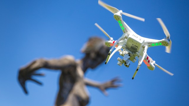
It may sound like the buzzing of a swarm of bees, but it’s actually the whirring of the new DJI Phantom Vision+ quadcopter that we’ve been testing. We head out to Treasure Island to get some flying lessons and then sit down to explain why we’re so excited about RC drone technology. The first part of this video was actually shot with the Phantom 2 Vision+!
Ultimate Prop Wishlists – 4/8/2014
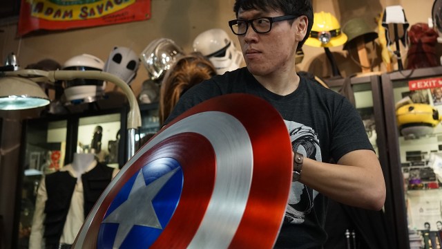
This week, Adam, Will, and Norm discuss their prop wishlists, the things they’re always on the lookout for in a variety of categories. Also discussed: the new Cosmos, the old Cosmos, and The Truman Show. Apologies for the lost video in the final minutes of the podcast. Our GoPro failed midway through the recording.
Premium: Will and Norm Visit the Game of Thrones Exhibit

In preparation for the season premiere of the new season of Game of Thrones, Will and Norm visit the traveling exhibit to admire the costumes and props from the show. We were only allowed to shoot video using smartphones in the exhibit, but you can also find our photos here.
The Zoidberg Project, Part 10: Mold Finishing and Foam Latex
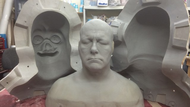
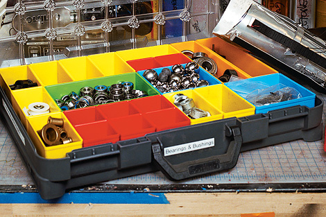
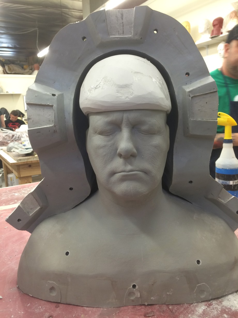
The primary mold for the Zoidberg sculpture is complete, but there are still a few things to do to make this mold functional for casting masks. The first thing I need to do is to drill the bolt holes and add T-nuts to the flange of the mold (the flat parts around the outside that connect the two halves together). Because of the rigidity of the flange, I don’t need to put a gajillion bolts in it to keep the mold stable. I start by drilling in a few typical places: near the bottom at the end of the flange, in the middle (corner of the neck) and up at the top of the head (one on either side of the large registration key).

When I’m placing my bolt holes, I need to pay attention to how close/far away from the sculpture they are. I like getting them as close to the sculpture as possible to keep the mold tight, but keeping in mind the outside of the mold–meaning that if I put the hole too close to the sculpture, I won’t be able to get a bolt through the flange. This usually ends up being about an inch or inch and a half from the sculpture. Sometimes, my process leaves a bunch of extra land on the flange, but I like having that extra land for when I’m prying the molds open. If the flange is too short, you can barely get a pry bar or screwdriver in between them to get any leverage for prying. It’s all about finding happy mediums.
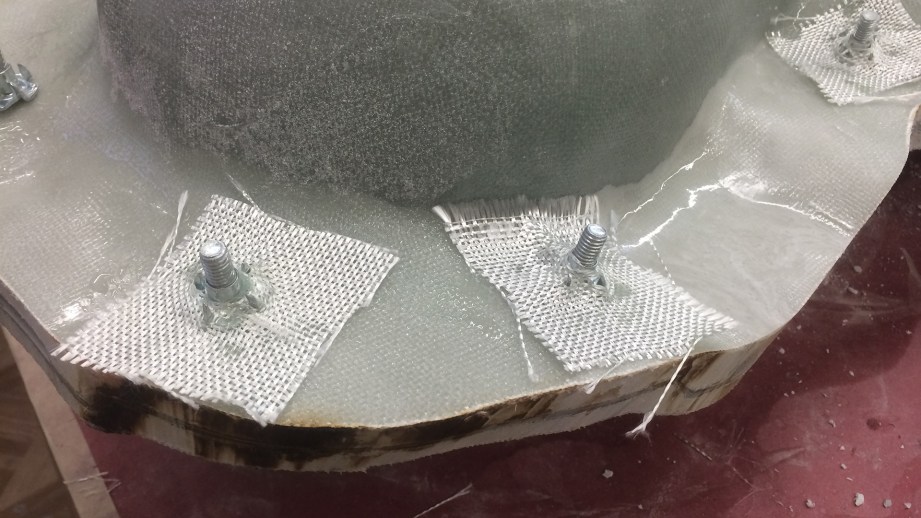
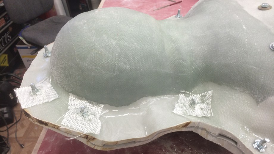
To make the mold easier to open and close, I love using T-Nuts. These are little nuts with a flat flange and teeth on them. This makes it so I can glass them onto the outside of the mold and then they won’t spin. Since I don’t have to fumble with the nuts when bolting and un-bolting the mold, I have the t-nuts permanently attached on the back side. To do this, first I brush a little wax onto the bolt (just to ease the removal) and tighten the T-nut onto it. I cut small squares of the glass cloth and mix up a small amount of freefrom air dough. By spreading the weave a tiny bit in the center of the square, I can push it over the T-nut and laminate it onto the flange with a little Epoxamite 102. Then I’ll take a tiny bit of dough and put it around the T-nut and laminate one more square of glass to sandwich it all together. Once this is set up, I’ll trim any glass that might be hanging over the edge, and back the bolts out and sand off any glass or resin that is still sticking up where the bolt used to be.
On both the head and the tentacle molds, I need to make another core-insert to accommodate where the animatronics will eventually be housed. The size of this core insert is determined by how thick the sculpture is, so I have to figure out how much space I have. I took the extra time to only scrape half the clay off the core, so I could see a cross section of the sculpture thickness. It doesn’t always work out this way, sometimes the clay will stick to the negative part of the mold, and then I can’t use this trick. I just happened to luck out. When I look at the cross section of the clay thickness I see that I have plenty of room in the top of the head, and I think I can core about 3/8″ out of there and not have any risk of seeing a lump in the top of the head when I put in the core-insert.
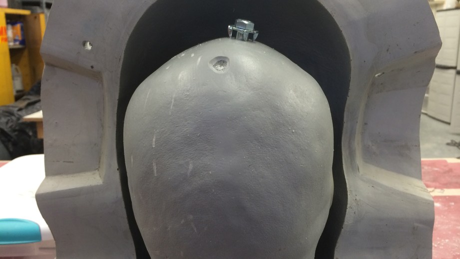
Using the clay cutter I’ve previously made with multiple thicknesses, I use the appropriate side to cut a bunch of slabs of water clay (em210) and press them into the negative. This is all covered with some plastic wrap to ease in the cleanup. On the top of the core, I also want to make some registration points for this insert. I have a few sizes of round router bits that I use as a key cutter, and use those to buzz in three contact points in the top of the head. I then drill a hole where the bolt that holds the core in will go. I wax up the top of the head core, add a bolt and then spin on a T-nut, but this time facing the other way. With a little bit of glass cloth and some epoxamite, I thread it in between the teeth of the T-nut and tap it down. This will make the contact point and bolted section stronger and resistant to pulling out of the insert a bit. By confirming with the picture of clay half removed from the core, and a picture of the core just set inside the negative, I can visually estimate how much volume I think it’s going to be, and mix up that much freefrom air. Some of this will get pressed onto the top of the head, and some will get pressed onto the plastic wrap, then the whole thing closed and bolted up. The next morning, I can crack it open, clean the water clay off, and pop this new core-insert off the head, and sand the edges smooth and even on a belt sander.
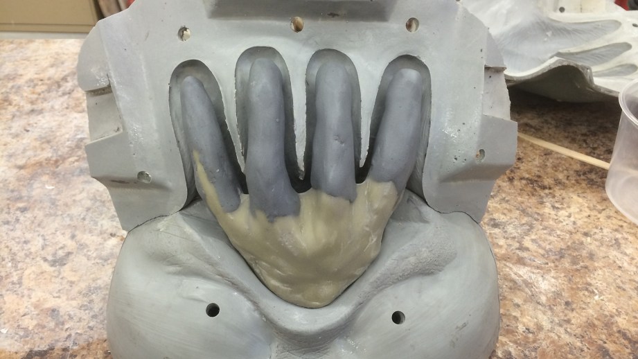
Now I need to do a similar process for the tentacles. First I hit the whole thing with Ease Release 200 to make sure the resin that I will inject won’t stick to the mold, then I take some soft Sculptex clay and roll it out to about 3/16″and lay this into each half of the negatives. This will represent the thickness of foam latex I will eventually get. On the positive section of the mold, I drill a hole in the center and put a bolt and T-nut on there. I also drill two small ¼-inch holes on either side to serve as injection points for the resin. Once this is all bolted back up and turned upside down, I grab a large syringe and inject some Smooth Cast 380 into one hole, and plug the other one with a small wad of clay as soon as it starts flowing out. If I leave the syringe in there it will maintain a bit of back pressure and the resin level will not drop. Once this is set up in about two hours, I can crack it open and clean everything out. This core is a little misshapen for my taste, so to just round out the “fingers” I Drexel down the sharp points and then use a little pro-poxy to beef up the forms and smooth it all out. Boom, now the core-inserts are done!!
Now comes the foam run! My friend Roland Blancaflor is the best foam runner in the industry and has some mystical formulas and additives and methods to his madness, which I don’t even know. So I’ll just explain the basics of foam latex, which worked just fine for me until I met Roland and saw his amazing work.
First, a brief history of foam latex. In the 1930’s, makeup artist George Bau was making props from foam latex for Paramount. In 1937, Perc Westmore brought him into the Warner Bros makeup department, and he used it on films like “Hunchback of Notre Dame” and “The Wizard of Oz,” among others. 1955 was the first year that Dick Smith (The Godfather, The Exorcist) used foam latex in production, which was taught to him by George Bau. in 1974, Bau gave his formula to Charles Schram, and in 1985 he sold it to Tom Burman. Tom burman employed Gil Moscow who broke off and make GM foam, which was sold off a few years ago to Namies Beauty (who now owns Burman Industries). In 1978, Tom McLaughlin started working for Jim Henson on The Dark Crystal, and eventually compounded his own foam system too. This was later taken over by Alcone. Then in the early 2000’s Monster Makers hired Tom to re-compound the foam, and it has been since reformulated again and is Monster Makers’ own brand. There’s a long history to the many uses and formulas of foam latex, and my point is that it’s not the same material that has been used in Hollywood since the 30s–each variation has a life and legacy of its own.
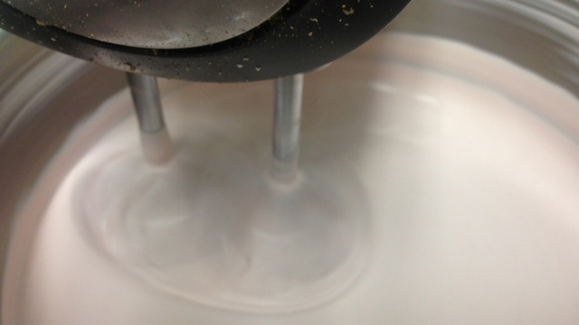
Foam Latex is typically four components that need to be accurately measured out and added at different times in the run schedule. First is the latex base, mixed with a foaming agent and curing agent in a Sunbeam, Kitchen Aid or Hobart mixer (depending on the volume that you are mixing). The first part of the mixing schedule is a fast speed, meant to whip the latex into a froth. Then the next steps are slower speeds–refining stages meant to break the large and inconsistent bubbles down into smaller and more consistent sizes. Finally, the last stage is a slow speed where you add in a gelling agent that will cause the foamed latex to congeal.
The amount of this additive and variations on the time of the first few stages will help predict the amount of time you have to get the foam injected into your mold. There are also other additives available to add to your concoction. Some are flow increasers that help the mixture flow into small details, some are stabilizers to help the foam cure up if it’s too cold or hot or there are other inconsistencies. And there are softeners you can add too. Once this is all mixed and injected into the mold, it needs to be baked. This epoxy that I used is not rated for high temperatures, so it needs to be baked at under 140 degrees. There are other epoxies that have upwards of 300 degree ratings, but I don’t need that for foam latex. 140 is plenty to bake the foam.
All of this is a skill that (like everything else) needs to be practiced and worked at. There are a million variables and things that can go wrong. This is why I now just take my molds to Roland. It’s just easier that way, and I don’t need to have an oven or whip up stinky latex in my shop.
Once it’s baked out, the mold is opened, and the skin can be taken off the cores. This first skin will just be a test skin. This is similar to what I sent Adam last year for his Admiral Ackbar mask before Comic-Con. I’ll use this to test paint, and evaluate thicknesses for the animatronics. Once it’s determined that the thickness is good enough, I’ll have Roland run another set and get the seams trimmed and patched up with smaller batches of foam latex and heat-gunned to bake the patched sections.
Today, there are a few brands of foam latex available, Monster Makers, Alcone, And GM. Pretty much any of these will work just fine with a little bit of practice and tinkering of additives and run times to suit your climate and elevation. Each of the brands comes with some info sheets with suggested run schedules and measurements. These are a good starting point, and with a bit of trial-and-error, you will find a schedule that works for you. Roland also has a pre-made prosthetic line that he sells to the general public. I have a few sculptures that I have done for him that are available to buy. Check his website or Facebook for info and pictures!
Thanks to Iwata-Medea and Smooth-On for providing materials and sponsoring this project.
Episode 251 – The Podcast of Truth – 4/3/2014

This week, Will, Norm, and Jeremy discuss the continuing implications of the Oculus/Facebook purchase, Oculus hiring Michael Abrash, rearview cameras in cars, Roku’s HDMI stick, Gmail’s birthday, Liars day, and DIY traffic jams. We recorded before BUILD and the Amazon Fire TV announcement, so expect to see that next week.
Inside Adam Savage’s Cave: Gladiator Armor
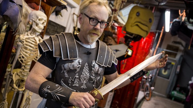
Adam geeks out over some new costume armor he just received: a movie-quality replica of Russell Crowe’s costume from his final fight in the movie Gladiator. The convention-ready costume was fabricated by Todd Coyle, who also made Adam’s Indiana Jones jacket that he’s worn on Mythbusters.
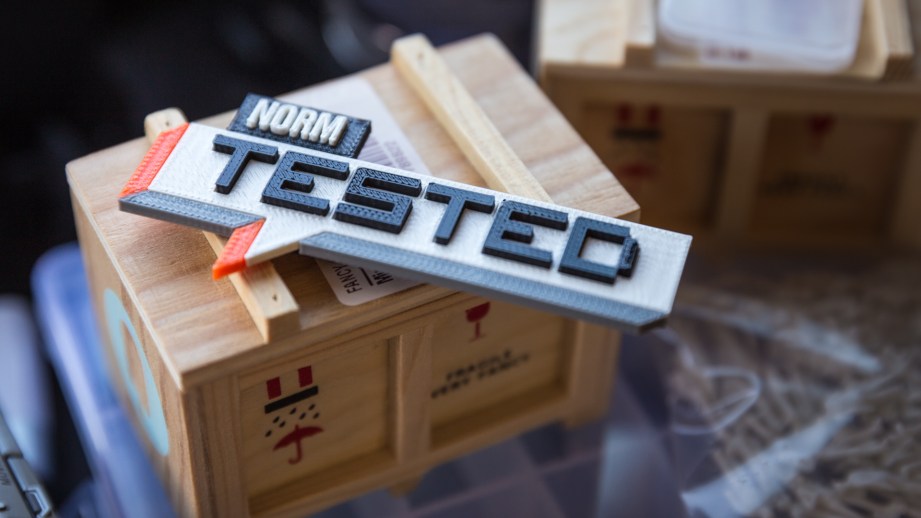
Bits to Atoms: Designing and 3D-Printing Tested Nametags

Sometimes a project pops into your head and keeps popping up–on the subway, at work, during meetings, while making dinner, laying in bed trying sleep, etc., until you just have to do it in order to purge it. It occurred to me that the Tested logo would be perfect for a 3D print! With its simple geometric parts as well as the opportunity to demonstrate a variety of printing techniques, I couldn’t resist. I had made name badges before for my booth at Maker Faire and thought it was a good idea for the Tested logo–the guys need to represent!
The first step was to simply sketch out how the logo would break down into parts for printing. Since the Tested logo is made up of simple shapes the break down and modeling were relatively simple.
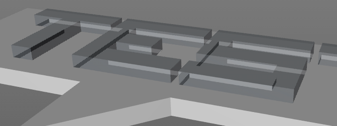
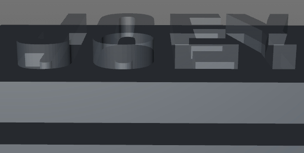
In the TARDIS article I mentioned using a backdrop picture to build on top of and Norm supplied me with some Tested logos files, not knowing what purposes they would be used for! A dimmed down version of the logo was used in the top view and the geometry was built right on top of it. Since mechanical precision wasn’t needed, a simple cube was stretched out and modified by eye to match up with each piece.
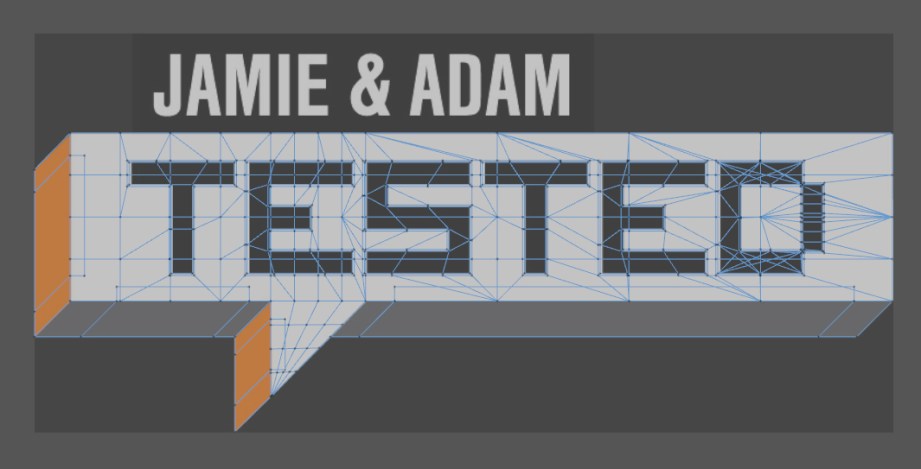
The ‘Tested’ text could easily be built from scratch since it’s so blocky, but there’s an even easier option if you can find the actual font, which is free at one of my favorite sources, dafont. Most modeling programs will have a text tool that will allow the letters to be extruded into 3D models which saves a ton of time.
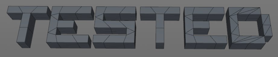
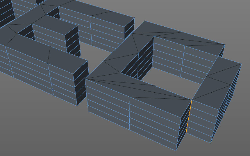
This can get a little messy since geometry is automatically generated, so keep an eye out for problems. In this case, the ‘D’ in ‘TESTED’ was an issue since it generated a non-manifold edge which, as we discussed last time, is when more than two faces are sharing the same edge, therefore creating impossible geometry. I fixed this by deleting the offending part, rebuilding it and printing it as a separate part from the rest of the ‘D’.
The next step was to decide how the text and the tag base would go together. My 3D printer and Tested’s MakerBot Replicator have two print heads and can dual extrude which means the white tag base could be printed first by one head and then the black text could be printed by the second, producing raised text. Or both the base and text could be printed concurrently so the text would be embedded in the tag. The problem is dual printing is still finicky and in particular, printing white and black at the same time tends to make a mess.
During printing with FFF, plastic bits end up on the print nozzle and when dual printing they almost always end up in the other color plastic. There have been printing improvements to minimize this, but there’s no way I was going to dual print a large white surface along with black and not get some boogers, so dual printing was out.
I could have just printed the letters and glued them to the tag but I didn’t want to deal with keeping them straight during gluing and drying so I made cut-outs for each letter. This was done by simply making a slightly enlarged copy of the text that was pushed down into the tag then subtracted from it with a boole function.
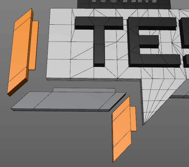
The trim pieces were very straightforward, made from slightly modified cubes, but extra attention had to be paid in order to make them fit properly. The digital model does not account for variances that will happen during printing due to the resolution, accuracy and properties of the material used. If I were to print the trim pieces right out of the modeling program as-is they wouldn’t fit quite right, most likely overhanging the edges of the tag. To compensate for this the trim pieces were reduced in size by .2mm which made them fit perfectly. This is usually a trial and error process and may even require some manual trimming with files or an x-acto. I also added a lip to the back which would help with alignment and provide more surface area for glue.
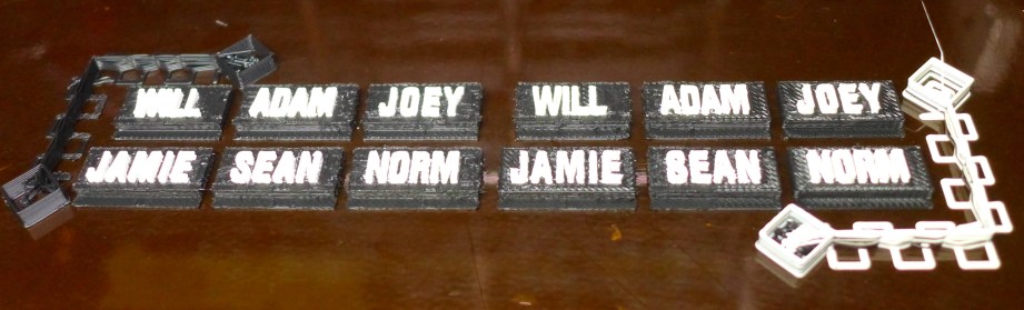
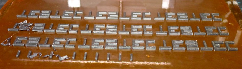
The name tag part of the badge presented another challenge. It was too small to print like the main portion. I attempted to do so but the letters were so small that the print didn’t turn out well and were difficult to fit in the recess.
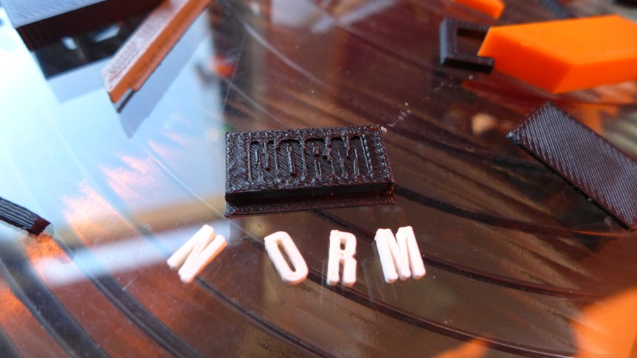
In this case I decided to dual print which worked out all right, since the main color was black, there was less white, and I could touch up any blemishes with some white paint.
Dual printing is easy to mess up since the two colors need to be brought in as separate objects and must remain in specific relation to each other to print properly.
Dual printing is a tricky business and easy to mess up since the two colors need to be brought in as separate objects and MUST remain in specific relation to each other to print properly. The prep for this is similar to how the ‘TESTED’ text was cut-out, except in this case the text is not enlarged. The ‘TESTED’ text was enlarged for cutting to allow for print tolerances so the finished product would fit together (just like the trim).
With dual printing, the two materials should fuse together and this is accomplished by cutting out a space which is the exact same size as the object which fills that space which causes the two materials to fuse together when printed.
The name text and base are brought into the slicing program together so they maintain proper spatial relationship to each other. Often the slicing program will ask if each object should be placed on the print platform and usually the answer would be ‘yes’. An object left hovering above the print bed will produce weird prints that start in mid-air. But in this case the answer would be ‘no’ since the text shouldn’t be on the print bed but on top of the base. Selecting both the text and base and then placing them on the print platform will keep them properly aligned.
When printing the ‘TESTED’ letters I made extra since printing very small parts can be challenging as they will often pop off the print bed. I also flipped them upside down so the face would print against the smooth finish of the bed and produce a nice shiny surface finish.
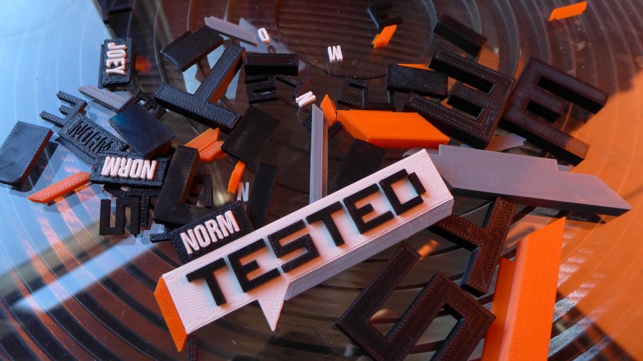
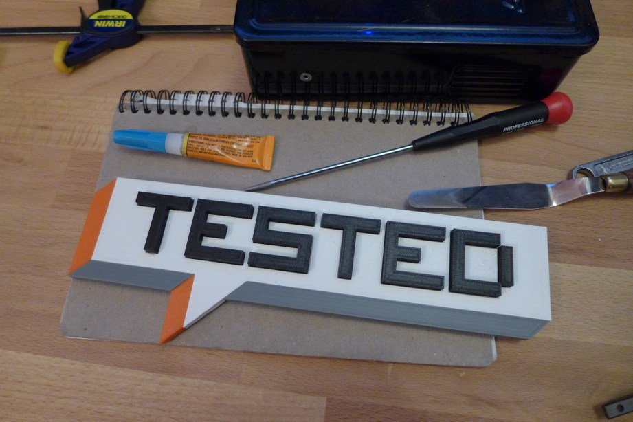
With all the parts successfully printed, they were glued together which was facilitated by the cut-outs for text and the trim tabs. ABS and PLA parts can easily be glued together with superglue, I really like Gorilla Super Glue Gel because it usually doesn’t leave white residue from fumes and it’s slightly rubbery which allows for a little give between the parts.
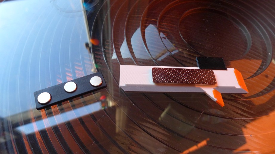
The final touch was a magnetic badge holder which doesn’t mess up clothes (but watch out for your pacemaker) and allows the badge to double as a fridge magnet.
After the name tags were done, I was inspired by Carl Merriam’s great LEGO Tested logo to print one as big as possible. Since it’s digital, I just needed to enlarge all the original pieces an equal amount and print.
This ended up being a really fun weekend project and Will and Norm seem to like them, which is the greatest gift of all. Awwww! Would you like to know more? Ok! I also did a video walkthrough so you can see it all in 3D! See you next time!
Premium: Will and Norm Geek Out at the Mondo Gallery
While in Austin for SXSW, we made a trip to the famous Mondo art gallery for a special exhibition of Disney movie posters. Norm gets indecisive about what screenprints he wants to buy, but it all works out at the end!